How to expand output of pot

Thread Starter

Ian Harris

Joined May 4, 2016
29
Hi All,

I am trying to build an Arduino based R/C transmitter for model aircraft. Got everything working, but have a small problem with the control pots on the sticks. They are 5k pots, but only a small range of the pot is used. When I read them with the Arduino I typically get values between ~400 and ~620, so a range of only about 220. The adcs on the Arduino are 10 bit resolution, so can theoretically measure from 0 to 1023. I can do some software trickery with multiple reads an averaging, but I would rather begin with a more accurate reading.
Based on my results I am getting between ~2v and ~3v for full stick travel. I'm wondering if it's possible to improve that electronically, i.e. convert 2v to 0v and 3v to 5v in a fairly linear fashion.
In my searching it seems what I need is a DC boost converter, maybe like this one on banggood.com. Set of 10 for $10 seems pretty good to me, but is this the way to go? My electronic knowledge is zero, zip, zilch, nil, nada, nothing, so I'm looking for some advice on a) if this is possible, and b) if it is how to do it.
All advice gratefully received.
;-) Ian
 

ericgibbs

Joined Jan 29, 2010
21,532
hi Ian,
Welcome to AAC.
Your link page is coming up blank,?
Using amplifiers it is possible to shift to zero volts and expand the range to 5v.

E
 

Picbuster

Joined Dec 2, 2013
1,062
if value is running from 400 to 620
test if input >= 400
{
int value = (input - 400) * 4
}
value will run now from 0 to 880
map value to range wanted.

Picbuster
 

danadak

Joined Mar 10, 2018
4,057
Analog to
Digital
Converter
Features • 10-bit Resolution• 0.5LSB Integral Non-linearity• ±2LSB Absolute Accuracy• 13 - 260µs Conversion Time• Up to 76.9kSPS (Up to 15 kSPS at Maximum Resolution)• 8 Multiplexed Single Ended Input Channels• 7 Differential Input Channels• 2 Differential Input Channels with Optional Gain of 10x and 200x• Optional Left Adjustment for ADC Result Readout• 0 - VCC ADC Input Voltage Range• Selectable 2.56V ADC Reference Voltage• Free Running or Single Conversion Mode• Interrupt on ADC Conversion Complete• Sleep Mode Noise Canceler

Note the A/D can be differential, use - input with offset to min value, and it has a 10X
capability in one channel. So 300 mV change can be 3V change.

https://electronics.stackexchange.c...al-analog-signal-conversion-using-arduino-uno


Regards, Dana.
 
Last edited:

ebp

Joined Feb 8, 2018
2,332
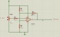
This is a simple gain and offset problem that can be done with a single op amp. Any "rail-to-rail" op amp would do - neither speed nor precision is important here, but the ability of the output go get very close to the supply rails.

I don't have schematic tools on this computer, so just words, but the circuit is simple. Perhaps someone else will draw the circuit for you. Eric is good at that and might even show a simulation for you.

non-inverting input of the amplifier straight to stick output

inverting input of the amp
- 20k to output of amp (feedback)
- 10k to common (ground)
- 10k to +5 V
It is the resistor ratio that is important, not the absolute values; 20k and 10k are common values; 1% resistors would be best,

The +5 V to the last-listed resistor would be the supply for the Arduino, assuming it uses its power supply as the voltage reference for the ADC.

It might actually be better to use slightly lower gain so that the there was a little margin in the output signal from the amp. In this case, the feedback resistor would be reduced in value slightly (e.g. 18k would yield 0.2 V to 4.8 V).

Regardless of which method you choose of those that have been suggest, I recommend reading the ADC perhaps 8 times and averaging. The sum of 8 readings will fit nicely into a 16 bit interger and the division is a simple shift operation so it is fast (that's if the compiler does it as a shift instead of calling a general-purpose division routine). Don't use floating point for anything related to this unless you have some compelling reason to.
 

Thread Starter

Ian Harris

Joined May 4, 2016
29
Thanks to all for you feedback, much appreciated.

@ericgibbs I don't have a web page, not sure where you are looking. I couldn't see anything in the profile that referred to a webpage.

@Ian Rogers good idea, but I'm looking for a bit more than 300 resolution, more like 1000 if I can get it.

@Picbuster you're right I could do it in software, but the resolution remains the same, but instead of 400, 401, 402 etc, I get 1000, 1004, 1008 etc. i.e. still 220 odd "ticks" from one end to the other. Using multiple reads and averaging, as suggested by @ebp is a way of improving resolution and I have done quite a bit of experimentation with this technique and had some success. I've also looked at a number of libraries for smoothing and "conditioning" the output of the analogRead, particularly as the raw output has a lot of huge spikes, that smooth the output using various techniques. I'm currently using one called RunningMedian that seems to work pretty well and is easy to use. However they all, by definition, are basically fudging the output (and introducing lag). Hence my quest to see if I can improve the raw reading from the analogRead. I have also experimented with writing my own analogRead using the atmega328 registers, as my understanding is the Arduino analogRead is quite inefficient, as it sets all the adc registers, does the analog read, then unsets all the registers again. Presumably to make things simple (you don't need to setup the adc in Setup(), then read it with another command in the loop() section, worry about interrupts etc). I didn't get very far with it though.

@danadak where did you get the quote from about the adc? I'm interested in learning more about the gain mentioned, but there is nothing in the atmega328 (for the Arduino Nano, which is what I'm using) spec about it. Or are you talking about the AD8237 op amp mentioned in the link?

@ebp further to danadak's remarks, do you have a suggestion as to what device would be suitable? I need 8 analog inputs (for this project, I have another in the pipeline that will need 14...) so presumably twp quad amp device would be the go. What sort of characteristics should I be looking for?

Thanks again to all posters, much appreciated.
Ian
 

danadak

Joined Mar 10, 2018
4,057
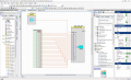
You could do this in PSOC. I used 12 bit SAR, it also has a 20 bit DelSig.

The VDAC sets range and offset. So if you set VDAC to 2V, then the 12 bit
range is

0.0 ± VDAC (Differential)–Input ± VDAC

If you need even more res you can use DelSig, 20 bits, along with analog mux.

This uses, as you can see, a fraction of the capabilities of the PSOC 5LP, which
is high end family. I think the PSOC 4 could do it with Sequencing 12 bit SAR, but
did not try this. PSOC 4 is low end part. Attached is component list for 5LP, a
component is an onchip resource in PSOC. PSOC 4 is a subset of the list.

The tool and compiler are free, the PSOC 4 board is $4, the 5LP $10.

http://www.cypress.com/documentation/development-kitsboards/psoc-4-cy8ckit-049-4xxx-prototyping-kits

http://www.cypress.com/documentatio...oc-5lp-prototyping-kit-onboard-programmer-and

The only thing I did not check is these small boards do not carry the total I/O
of the chip on the board, eg. will it route to the board pins actually present. I just
generically auto routed this in tool. Normally user picks pins to route to and
tool does rest.

http://www.cypress.com/products/psoc-creator-integrated-design-environment-ide

upload_2018-8-21_7-8-53.png


If you wanted to do just single ended measurements (save pins) you could use a
separate onchip mux, either DelSig or SAR, and use one of the onchip OpAmps
at mux out to do the offset and gain /scaling into A/D. Without doing actual design
that would for sure route on to the low end board.


Regards, Dana.
 
Last edited:

Kjeldgaard

Joined Apr 7, 2016
476
Here are some calculations for @Ian Rogers sketch in #9.

Supply voltage: 5 V
Input voltage: 2 → 3 V
Output voltage: 0 → 5V

Both the input and output voltage are symmetrical around 2.5 V
So I choose: R1 = R2 = 20 KΩ
The gain will be: (5-0) / (3-2) = 5/1 = 5 times
Since it is a non-inverting amplifier, R3 must be 4 times the parallel value of R1 and R2: 4 * 20 KΩ || 20 KΩ = 4 * 10 KΩ = 40 KΩ
R4 should then correspond to the parallel value of R1, R2 and R3 = 8 KΩ, but I would probably choose 10 KΩ
 

ebp

Joined Feb 8, 2018
2,332
The MCP6001 that Ian Rogers suggested is a good choice. It is a single amp, but there is a dual (6002) and a quad (6004).

With this amplifier, I would probably set R4 in Ian's schematic to at least 20k ohms. For this amp, it has almost not effect on the signal (normally such a resistor is used for reducing "offset error" due to "input bias current", but for this amp it makes nearly zero difference), but it will protect the input of the amp in the event that the joystick has power but the amplifier doesn't and improves protection of the amp against electrostatic discharge (ESD), which is always a bit of a risk with something connected to touchable things.
 

danadak

Joined Mar 10, 2018
4,057
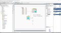
This is low end solution, PSOC 4, that should work just fine.

This is single ended A/D so saves pins.

Attached.

In both solutions you are digitizing a 1V range, 2V - 3V, to 12 bits resolution.
The DelSig solution, if used, would take you to 20 bits, probably
effective somewhere around 16 bits.

Regards, Dana.
 

Attachments

Last edited:

Thread Starter

Ian Harris

Joined May 4, 2016
29
Wow! Thank you very much to all who have posted here. You've given me a *lot* to digest! I'm looking forward to working through all your suggestions and finding a solution that works for me.
I'll be back to post what I've done.
Thanks again,
Ian
 
Top