How to drive a 5 wires stepper motor without Arduino ?

Thread Starter

Philexium

Joined Oct 15, 2017
111
Hi !

I want to find a schematic showing how to drive a 5 wires stepper motor without Arduino and coding.
Beware it is a 5 wires motor (most schematics and chinese modules use a 4 wires model).

I have the motor 28BYJ-48 a very 5 volts popular model.
I use the ULN2003 driver module.
I need to control :
  • The speed with a pot. (about 1 complete turn in 30 seconds)
  • Stop/start with 1 button
  • Direction with 1 button
Thanks in advance for your help
 

Attachments

Jerry-Hat-Trick

Joined Aug 31, 2022
853
Maybe a 555 astable into a 4017 ic into the ULN2003, but to reverse the direction a 4 pole double throw switch between the 4017 and the ULN2003. But a processor is a simpler and less expensive solution
 

JohnSan

Joined Sep 15, 2018
141
You can convert that motor to a bi-polar configuration, then use an A4988 driver, not needing an arduino or cpu of any description.
Search online for the instructions. Basically, lift the tabs, slide the case back. Cut a wire, then it's bipolar and easier to drive.
 

MrChips

Joined Oct 2, 2009
35,276
Or you can use a CD4017 Johnson counter to create a 4-phase sequencer for full step action. Half step will be a bit more tricky.
 

sarahMCML

Joined May 11, 2019
706
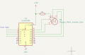
You can use the attached translator circuit to drive the ULN2003 board. All you need is a switch to ground attached to the Direction pin, and some form of pulse generator (a 555 timer?) to give you Step pulses. I haven't shown any decoupling capacitors on the circuit, you may wish to add a few. (Whoops, just noticed I've added pin 15 twice!)

Translator.png
 

MaxHeadRoom

Joined Jul 18, 2013
30,872
The advantage with the L297 & L298 combo is that the motor current can be monitored and set at the motor rated value, Important!
The only issue is that is intended for 4 wire motors, which is generally the prefered types due to higher torque.
 

MaxHeadRoom

Joined Jul 18, 2013
30,872
You can use the attached translator circuit to drive the ULN2003 board. All you need is a switch to ground attached to the Direction pin, and some form of pulse generator (a 555 timer?) to give you Step pulses. I haven't shown any decoupling capacitors on the circuit, you may wish to add a few. (Whoops, just noticed I've added pin 15 twice!)
Where is the ability to set motor rated current limit?
Important !
 

sarahMCML

Joined May 11, 2019
706
Where is the ability to set motor rated current limit?
Important !
Not needed if using that translator circuit to drive the ULN2003 module with the 5V, 5 wire motor. But it does work well with an L298 module and the motor modified for 4 wire mode. Motor supply needs to be at least 10V though, due to driving twice the resistance and four times the inductance.
 

Ya’akov

Joined Jan 27, 2019
10,355
For your five-wire 28BYJ-48, consider two microcontroller-free designs. The OSSteD – Old School Stepper Driver uses discrete logic and adjustable speed. Also see Driving a Stepper Motor Without a Microcontroller. Both offer useful starting points for your project. Your ULN2003 module can drive this unipolar motor. You need a potentiometer for speed adjustment. Add push buttons for start/stop and direction reversal. Verify both designs support these controls before building. Target approximately two revolutions per minute for your application.
Have you built either of these yourself?
 

panic mode

Joined Oct 10, 2011
5,420
current can be limited externally. for a cheap and simple current limit add resistor or light bulb on +ve side. or you can add LM317 as current limiter

1792602536893.png
 
Last edited:

MisterBill2

Joined Jan 23, 2018
28,499
Oh Wow!! Please understand that stepper motors have been around since long before processor modules were even a dream!! All of them had SIX wires, and the current was set by means of a series resistor dropping the higher voltage supply. THAT was done to allow faster response and higher speeds, by compensating for the problem of the motor inductance limiting the maximum step rate.
OF COURSE, Efficiency suffered terribly!
BUT "Superior Electric" brand steppers were doing all sorts of things in factories since they were so much simpler that cams and gears, and so much cheaper and easier to adjust.All it requires is the four phases and a bit of logic to supply the sequence, either full step or half step.
 
A practical point on the wiring side, since the 5-wire version is often misidentified: find the common wire with a resistance meter before connecting anything. The common-to-any-coil reading is roughly half the coil-to-coil reading, because each coil-to-coil measurement goes through two half-windings in series. Wire that common lead only to the positive supply, never to a driver output. On the ULN2003 board, make sure the COM/freewheel pin is tied to that same +5 V rail, otherwise the inductive kick from each phase has no clean path and you get ragged stepping and occasional resets of the logic. Keep the motor leads short, and keep the 555/4017 ground and the ULN2003 ground joined at one point close to the supply entry - the phase currents pulse through that return, and if the logic shares a long thin ground wire with them, the counter sees the voltage bounce as extra clocks. For your speed target, remember the output shaft is geared down about 64:1, so one output turn in 30 seconds needs a much faster motor-side step rate than it first appears; set the oscillator range from the motor-side number, not from 1/30 Hz. Reversing direction is cleaner by reversing the phase sequence at the counter outputs than by swapping motor wires, which on a 5-wire motor only disturbs the common/coil relationship you just identified.
 

MisterBill2

Joined Jan 23, 2018
28,499
Evidently this thread is concerned with much smaller steppers than I have worked with.
And I see no mention of the half-step and full step modes.
Half-step doubles the resolution ability, if running open in an loop mode, without an encoder.
 
Top