How to draw the Specific plots and curves in LTSpice?

Thread Starter

Mike2526

Joined Nov 10, 2020
110
Which magnetic core do you use (dimensions and material)? Ampere turns are important. I also have a model with a non-linear core.
Sir, I am interested to use a Toroidal transformers and material you can suggest me (cheaper is good, but with good efficiency). hope you can understand, what I mean to say. Thanks in advance for your kind cooperation.
 

Bordodynov

Joined May 20, 2015
3,431
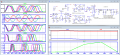
I applied a toroidal core. He is far from saturated in the scheme. After the transformer, a decent signal is obtained. But it's bad after the filter. The filter is bad! I have deduced the total power consumption and the power on the transistor. power on load. I gave a more optimal signal. I advise you to reduce the supply voltage. Since the signal is small, it can be done.
I'm uploading a diagram, but in order to open it, you need to have my model library.
expe.png
 

Attachments

sparky 1

Joined Nov 3, 2018
1,218
Torroid calculator link.
https://toroids.info/FT23-43.php

The simulation is good. On the bench the resonance check is a good idea.
The resonance found using 10 turns procedure, this also gives the needed information to find the AL value.
In the video below a much larger toroid is being checked However, the method is the same for 0.23 inch OD toroid
The math shown in video illustrates difference in uH, which is helpful if you need wider bandwidth, he has both 31 and 43.
The frequency limitation that an IRF510 I am not sure, the 43 good choice. For higher frequencies use an RF mosfet with higher Ft
The 3:1 reduces the voltage resulting in a corresponding increase in current, a profound improvement shown transformer simulation above.

 
Last edited:

Thread Starter

Mike2526

Joined Nov 10, 2020
110
I applied a toroidal core. He is far from saturated in the scheme. After the transformer, a decent signal is obtained. But it's bad after the filter. The filter is bad! I have deduced the total power consumption and the power on the transistor. power on load. I gave a more optimal signal. I advise you to reduce the supply voltage. Since the signal is small, it can be done.
I'm uploading a diagram, but in order to open it, you need to have my model library.
View attachment 333381

Dear Sir, thank you very much for sharing progress and the detailed message regarding the toroidal core and the transformer. It sounds like you have made significant strides in improving the signal quality, and I will modify the filter stage then share all my results with you (Should I choose the "Zin" and "Zo" 5o ohms for filter/matching network, right Sir?).
Regarding the "pout" graph, how draw the "pout" graph? Yesterday I tried several times I can get all other graphs, but Pout was missing. but here you uploaded. So, need your help for this matter as well.
Thank you once again for your Kind help.
 

Thread Starter

Mike2526

Joined Nov 10, 2020
110
Torroid calculator link.
https://toroids.info/FT23-43.php

The simulation is good. On the bench the resonance check is a good idea.
The resonance found using 10 turns procedure, this also gives the needed information to find the AL value.
In the video below a much larger toroid is being checked However, the method is the same for 0.23 inch OD toroid
The math shown in video illustrates difference in uH, which is helpful if you need wider bandwidth, he has both 31 and 43.
The frequency limitation that an IRF510 I am not sure, the 43 good choice. For higher frequencies use an RF mosfet with higher Ft
The 3:1 reduces the voltage resulting in a corresponding increase in current, a profound improvement shown transformer simulation above.


Dear Sir, thank you very much for sharing the toroid calculator link and the valuable insights you provided regarding the resonance check and the method for finding the AL value. I appreciate the guidance you have given on using the 10 turns procedure and the video that illustrates the difference in uH, which will be helpful for achieving a wider bandwidth. I am currently working on implementing the modifications you suggested and will take your advice into consideration as I proceed. I am grateful for your suggestion regarding the choice of IRF510 and the use of an RF MOSFET with a higher Ft for higher frequencies. Additionally, I understand the importance of the 3:1 ratio in reducing voltage and increasing current, as demonstrated in the transformer simulation.
Once I have completed these modifications, I will be sure to share all the results with the group. Thank you once again for your kindness and support.
 
Top