How to Design LED Driving Circuit for RGB LEDs

Thread Starter

kenn2323

Joined Jul 18, 2019
17
They are polarity sensitive- the extra diodes inside protect the LED's from damaging reverse voltages.
The package has 8 leads- all the connections are available so you can configure the drive any way you need.

An LM3414 for each color will be very efficient and relatively simple- each one can be controlled by a PWM input via the DIM input.

To drive two LED's- connect them in series.

The biggest challenge is mechanical- these beasts need proper SMD mounting with a significant heatsink.
Can I have a circuit diagram of how to put these together to make the LEDs work?
Thanks
 

BobaMosfet

Joined Jul 1, 2009
2,211
I think a question that should be asked (sorry if I missed it), is what is the intended purpose? That can control how a circuit is designed to support the objective. If this is purely educational, then 3 transistors, appropriate resistors and a few other discrete components and/or logic gates could do all one needs.
 

dl324

Joined Mar 30, 2015
18,449
Can I have a circuit diagram of how to put these together to make the LEDs work?
Do you have a preference for driving the LEDs (high side vs low side)?

If you drive low side, you can use a logic level N channel MOSFET. If you want to drive high side, you can't drive a P channel MOSFET directly with a 5V control signal.

Low side driving is straightforward.

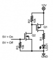
For high side driving, you'd have to do something like this:
upload_2019-7-19_7-56-33.png
Times 4; one for each color.
You could use bipolar transistors, but you'd need to do calculations for current.

Dissipating heat in the LEDs is going to be an issue.
 

Thread Starter

kenn2323

Joined Jul 18, 2019
17
I think a question that should be asked (sorry if I missed it), is what is the intended purpose? That can control how a circuit is designed to support the objective. If this is purely educational, then 3 transistors, appropriate resistors and a few other discrete components and/or logic gates could do all one needs.
It's just for educational purpose. Is there a circuit diagram that I can use as a reference.
 

SamR

Joined Mar 19, 2019
5,526
You guys are trying to make this difficult and it is not. It is a simple exercise for the Uno ramping PWM up and down on 3 pins that I have done before. Since I suspect this is a school assignment I will leave it at that. Typically done with one RGB but easily doubled in or out of sync.
 

Thread Starter

kenn2323

Joined Jul 18, 2019
17
You guys are trying to make this difficult and it is not. It is a simple exercise for the Uno ramping PWM up and down on 3 pins that I have done before. Since I suspect this is a school assignment I will leave it at that. Typically done with one RGB but easily doubled in or out of sync.
Can you show me a picture of how you connect them together?
thanks
 

Thread Starter

kenn2323

Joined Jul 18, 2019
17
Do you have a preference for driving the LEDs (high side vs low side)?

If you drive low side, you can use a logic level N channel MOSFET. If you want to drive high side, you can't drive a P channel MOSFET directly with a 5V control signal.

Low side driving is straightforward.

For high side driving, you'd have to do something like this:
View attachment 182040
Times 4; one for each color.
You could use bipolar transistors, but you'd need to do calculations for current.

Dissipating heat in the LEDs is going to be an issue.
One for each colour means I need 8 circuits for 2 LEDs?
 
Last edited:

SamR

Joined Mar 19, 2019
5,526
These are what are typically used and will not require switching transistors and can be driven by the Arduino directly. Note that these are common anode and you want common cathode.

https://www.aliexpress.com/item/32423998570.html?spm=a2g0o.productlist.0.0.451f56e6gOm1QK&algo_pvid=ae16977e-7f13-4dac-ac55-cf2786016a9f&algo_expid=ae16977e-7f13-4dac-ac55-cf2786016a9f-2&btsid=1ade4b92-159e-4658-a368-fbfd8f08bd34&ws_ab_test=searchweb0_0,searchweb201602_4,searchweb201603_52

It will require 3 pins, one for each color or 6 if you drive each LED separately.
 

dl324

Joined Mar 30, 2015
18,449
What are the problems with surface mount LEDs?
In your case, the main problem will be dissipating heat. 350mA through all 4 will dissipate around 3W. Read the datasheet to find out what the junction temperature will be without adequate heat sinking.
 

Thread Starter

kenn2323

Joined Jul 18, 2019
17
In your case, the main problem will be dissipating heat. 350mA through all 4 will dissipate around 3W. Read the datasheet to find out what the junction temperature will be without adequate heat sinking.
So can i mount it on a heat sink?
 
Top