The question needs a little more detail before any real answers can be generated.
For starters:
Fixed or mobile?
What will be the signal source; what are the electrical characteristics of the source.
What kind of modulation?
Does it need to be linear?
What will its load be; what are the load characteristics?
Any unusual constraints; size, weight, ventilation, etc.?
--Apart from anything else--
If you are contemplating a 'no tune' design, please be advised that the proposed 'coverage ratio' (cip ~ 4.322 octaves), as opposed to the bandwidth itself, poses formidable challenges...
Basically I want to apply the output of this RF amplifier for testing of a Piezoelectric device. So we need to provide a voltage between 50 V - 180 V and a frequency of 10 MHz to that device.
It can be anything either fixed or mobile where less effort and less budget will be required.
Its sinusoidal type of signal need to be generated. Yes it should be linear. load will be 50 Ohm.
Regarding constraint, for the time nothing is mendatory but it should successfully generate the required output.
One of the equipment is already available in market but the budget is too high so unable to purchase. The link for the same is given below.
So... You wish to generate a fixed 10MHz signal...?
Note that a Piezoelectric resonator/transducer will not present a 'nice' 50+0j load --- you'll need an adjustable matching network OR an arrangement incorporating the load as part of a power oscillator's 'tank' (a common technique in high-power signal generation)
IMESHO -- Your best approach is that of the afore mentioned power-oscillator scheme --- It offers the advantages of frequency agility and self (actually, implicit) matching...
If you want one for testing you're better off buying one. Cost should be in the $1200 to $3600 range. Without some RF design experience and some pricey test equipment I doubt that you could accomplish the design and construction any time soon.
If you want one for testing you're better off buying one. Cost should be in the $1200 to $3600 range. Without some RF design experience and some pricey test equipment I doubt that you could accomplish the design and construction any time soon.
Thanks, @Papabravo! --- I wanted to say the same thing - howbeit, having been thrice accused of being 'born with the silver spoon in my mouth' I was a bit 'shy' --- Seriously @Basudeb Behera we're talking pennies! Moreover, as I'm certain you realize, money is as nothing by comparison with time!
Thanks, @Papabravo! --- I wanted to say the same thing - howbeit, having been thrice accused of being 'born with the silver spoon in my mouth' I was a bit 'shy' --- Seriously @Basudeb Behera we're talking pennies! Moreover, as I'm certain you realize, money is as nothing by comparison with time!
Most of us were not born with silver spoons to eat our pablum. What we have learned and what we can accomplish is the result of the patient application of time and resources. Building wealth over a 30 to 50 year time horizon is doable by anyone. Doing it in a couple of weeks or months is nearly impossible. If you want to play in the electronics sandbox you need to adjust you expectations to your own reality and not throw stones at the folks who did it a different way.
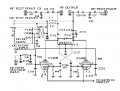
I had something like this in mind -- However, for improved power handling and ruggedness, I'd design the circuit 'around' a pair of 4CX250Bs as opposed to 6146s...
Addendum: IMNSHO, owing to their well-neigh 'bullet proof' nature, electron tubes are the only way to go with instruments of this kind!...
That basic approach should do it. Have to admit that I am mystified by the -12V on the plates. If necessary, the TS could use plug-in coils to change bands.
Question: Does the TS/OP have the requisite knowledge to fill in the missing component values? If not the schematic is not much use without a bill of materials and some idea of how the amplifier should be constructed.
Also the TS/OP mentioned budget constraints. Finding a source of working vacuum tubes is becoming harder and harder.
That basic approach should do it. Have to admit that I am mystified by the -12V on the plates. If necessary, the TS could use plug-in coils to change bands.
a power mosfet should be able to handle this, there are several ddesigns on the web about the irf840 in a broadband rf amp. and a higher voltage mosfet should be able to cover the power with no problems.
Tube vs MOSFET: We really don't know how much voltage is going to be needed to drive the transducer at 200 Watts. A secondary winding would make the application of MOSFETs much more likely.
Is that power to be dissipated/transmitted by the transducer or is that the reactive power?
The function of VR1, VR2 and the positive/negative 12v supply is to impose continuously adjustable -12V through +12V DC offsets upon each 'leg' of the output...
a power mosfet should be able to handle this, there are several ddesigns on the web about the irf840 in a broadband rf amp. and a higher voltage mosfet should be able to cover the power with no problems.
Actually the guys who repair antique radios that I know prowl the hamfests for vacuum tube bargains. Buying them from a commercial source with shipping can be expensive. A limited budget was mentioned.
Actually the guys who repair antique radios that I know prowl the hamfests for vacuum tube bargains. Buying them from a commercial source with shipping can be expensive...
If you want one for testing you're better off buying one. Cost should be in the $1200 to $3600 range. Without some RF design experience and some pricey test equipment I doubt that you could accomplish the design and construction any time soon.
I have checked everywhere, but you know its too costlier not like $1200 to $3600. Its more than $40000. Thats why only I am searching/approaching for an alternative root. If you kindly send some links where I can get the equipment with mentioned cost. It will be highly helpful for me.
Even I am seeking for the equipment with rent for some days from any source will be a great worth for me. The rent facility is available in US and Canada but not in India region.
 Facebook
 Google
 GitHub
 Linkedin