How to design a power amplifier circuit to achieve 20A output with operational amplifiers without distorting the signal?

Thread Starter

vincentuhd01

Joined Jun 27, 2024
19
I have some issues with this element of the ongoing problem statement.

Firstly, white noise, by definition, is noise with constant power spectrum i.e. a flat frequency spectrum over the bandwidth in question. At a guess, one could argue for white noise into a specific resistive load, say 0.6ohm (being 12v @ 20A). Since V/√Hz = √(P/Hz x R), P/Hz = V/√Hz^2/R = .001 * .001/.6 = 1.666μW/Hz. Over a 100MHz bandwidth that's something like 167W if my math is right.

Secondly, top of the range lab supplies from the likes of Rigol, Agilent/Keysight, etc have a noise figure of 350uVrms over a 20MHz band width, roughly equivalent to 350/√20e6*√100e6 = 783uV√Hz, over 100MHz BW so roughly in the ballpark of your test signal - how are you going to isolate that?
Regarding the required power of 167 W: I understand that 167 W might seem high, but could you please clarify why you highlighted this figure and how it could pose a problem for my project?

On the noise levels of lab power supplies: Yes, I am aware that the noise levels of lab power supplies can be an issue. This is something I am actively working on. I am currently in contact with the people responsible for the noise specifications that we need to inject into the board to understand the origin of these noise levels and to explore potential solutions to improve the situation.
 

Thread Starter

vincentuhd01

Joined Jun 27, 2024
19
Given that the noise will need to be isolated from the power supply output by a filter, that filter will also tend to block the noise contribution from the power supply. AND, given that the test requirement may require verification of the noise bandwidth, some adjustment may be required. Seldom is it wise to simply push ahead without being aware of just what one is actually doing.
If I understand correctly, the filters on the board we are testing will naturally attenuate the injected noise, and this is exactly the purpose of our tests. The goal of our testing is to ensure that, even if our power supply is noisy in a real-world scenario, the board will still function correctly. The noise specification is one aspect among many that we need to verify to ensure the board's robustness.

We are given a noise profile inspired by worst-case scenarios, and our task is to determine if the board can still perform under these conditions. The aim is to verify that the board operates correctly even after noise injection, ensuring its reliability and performance.
 

Thread Starter

vincentuhd01

Joined Jun 27, 2024
19
I have some issues with this element of the ongoing problem statement.

Firstly, white noise, by definition, is noise with constant power spectrum i.e. a flat frequency spectrum over the bandwidth in question. At a guess, one could argue for white noise into a specific resistive load, say 0.6ohm (being 12v @ 20A). Since V/√Hz = √(P/Hz x R), P/Hz = V/√Hz^2/R = .001 * .001/.6 = 1.666μW/Hz. Over a 100MHz bandwidth that's something like 167W if my math is right.

Secondly, top of the range lab supplies from the likes of Rigol, Agilent/Keysight, etc have a noise figure of 350uVrms over a 20MHz band width, roughly equivalent to 350/√20e6*√100e6 = 783uV√Hz, over 100MHz BW so roughly in the ballpark of your test signal - how are you going to isolate that?
Thank you for your analysis on noise specifications of laboratory power supplies. Regarding your mention of extending the noise figure to 100 MHz, I would like to clarify a few points based on the specifications of my Agilent N5767A power supply:

Noise Specifications of My Power Supply: For the Agilent N5767A, the noise and ripple figures are:

  • CV rms: 8 mV
  • CV p-p: 60 mV
Conversion to µVrms/√Hz: The RMS noise of 8 mV across a bandwidth of 20 MHz converts to approximately 1.79 µVrms/√Hz. Here is the calculation:

  • The RMS noise is 8 mV, which equates to 0.008 V.
  • With a bandwidth of 20 MHz (20 × 10^6 Hz), the square root of the bandwidth is about 4472.14 Hz.
  • The noise density is therefore 0.008 V divided by 4472.14, which results in approximately 1.79 µVrms/√Hz.

Questioning the Extension to 100 MHz: The power supply is specified up to 20 MHz only. Extending this specification to 100 MHz does not reflect the real capabilities of the power supply and could lead to a misinterpretation of its performance beyond its specified frequency range.

Approach to Noise Management in My Tests: In my setup, the noise I plan to inject extends up to 100 MHz, far beyond the intrinsic noise range of the power supply. I question the relevance of considering the power supply’s noise at 100 MHz, as it might overestimate its impact on my measurements at higher frequencies.

I hope I understood correctly and haven't made any errors in my calculations.
 

ronsimpson

Joined Oct 7, 2019
3,264
swept frequency test
I have been promoting that for too many posts. I use a vector network analyzer to make and inject a very low power signal into the power supply then read it back from the Device Under Test. I can't go to DC but can go to 10hz on the low end and only 2gHz on the top end.
 

Thread Starter

vincentuhd01

Joined Jun 27, 2024
19
REally, a swept frequency test, as an alternative, might work out very well unless it fails to detect some sensitivity that becaomes a problem later.
ok I note that this way of doing things is surely better but then what about the assembly to be done I don't understand if it really solves my problem in terms of mixing and increasing power
Could you explain in more detail the solution you imagine?
 

Thread Starter

vincentuhd01

Joined Jun 27, 2024
19
I have been promoting that for too many posts. I use a vector network analyzer to make and inject a very low power signal into the power supply then read it back from the Device Under Test. I can't go to DC but can go to 10hz on the low end and only 2gHz on the top end.
I understand that on the frequency band we are good but I think that I do not understand how you make this mixture with the analyzer on signal and the power supply and how the analyzer can be powerful enough to power my card with 20A and 12V, Would it be possible to be more specific about the solution you are using?
 

MisterBill2

Joined Jan 23, 2018
19,630
ok I note that this way of doing things is surely better but then what about the assembly to be done I don't understand if it really solves my problem in terms of mixing and increasing power
Could you explain in more detail the solution you imagine?
To add the specified noise to the supplied 20 amps power feed will require a series filter between the DC power source and the device being tested. The characteristics of this filter will be to present a fairly high impedance to the applied noise spectrum while putting less than an ohm of effective resistance to the DC supply current. Then the noise voltage will need to be supplied across the DUT (Device Under Test) power input thru an AC voltage coupling capacitance adequate to allow the specified noise voltage to be present on top of the DC voltage, at the DUT power input terminals. So while the functional description is fairly simple, the actual implementation may not be simple.
 
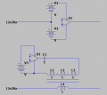
Pictured are two ideas I have used.
U1 is a power amplifier. V1 & V2 are shown as batteries but are isolated power supplies.
The power amp can lift or push down the 12V by some voltage.
1719937213625.png
Idea 2:
There is a transformer with 100:1 or 1000:1 turn ration. The amplifier puts an AC signal across the transformer and injects it into the 12v supply. By having a 100:1 turn ratio the 20A load will look like 0.2A to the amplifier.
The transformer will not pass DC and has a limited bandwidth. My network analyzer can remove (calibrate out) some of the transformer effects. You will probably need a low frequency transformer and a high frequency transformer.
 

MisterBill2

Joined Jan 23, 2018
19,630
Pictured are two ideas I have used.
U1 is a power amplifier. V1 & V2 are shown as batteries but are isolated power supplies.
The power amp can lift or push down the 12V by some voltage.
View attachment 326003
Idea 2:
There is a transformer with 100:1 or 1000:1 turn ration. The amplifier puts an AC signal across the transformer and injects it into the 12v supply. By having a 100:1 turn ratio the 20A load will look like 0.2A to the amplifier.
The transformer will not pass DC and has a limited bandwidth. My network analyzer can remove (calibrate out) some of the transformer effects. You will probably need a low frequency transformer and a high frequency transformer.
GOOD LUCK getting a transformer with the required bandwidth!! and ratio and current capacity.
 

Thread Starter

vincentuhd01

Joined Jun 27, 2024
19
I hinted that it cannot be done with one transformer. I have transformers for doing that job. I do this test when looking at the response of the power supply. (error amp testing)
thank you for your proposal and the schematics, unfortunately this is already what is done for the tests, and the whole issue is precisely to stop using a transformer which has had a lot of problems with this solution
 
OK, so a transformer does not work in this application, hence my "good luck" comment. so now the requirement is for a series filter for the positive supply line that will pass the 20 amps DC from the power supply and at the same time keep the noise voltage from being shunted by that supply . That will need to be a "band-stop filter for the entire frequency band used for the test, so it might be a series string of low resistance filter elements. The good news is that there is a lot of knowledge about band-stop filters.
 
Top