Facebook
 Google
 GitHub
 Linkedin
Hello to you all!
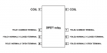
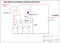
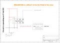
I have a DPDT relay HK19F 5 Volts/DC.
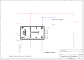
The relay is switched with an INPUT signal (see schematic enclosed)
The OUTPUT poles 5 and 3 switches 2 separate (off course) circuits.
Requested is: DELAY the OUTPUT of POLE 3?
Specification of ports:
1.The COM of the relay pole 7= + 5V
2. The COM of the relay pole 2 = -5V (GND)
3. Pole 5 NO is going to an attached circuit without DELAY and starts immediately
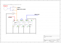
4. Pole 3 NC must be attached to an Adjustable TIME delay circuit:
Why is a time delay for the pole 3 NC needed:
with the relay I am switching 2 separate circuits. The first circuit will start immediately when the relay is triggered.
The second circuit will start a few seconds later. This 2nd circuit can only be operated when it is switched through mass/GND.
What I already tried:
1. potmeter, resistor capacitor (RC-network (DIGIKEY RC timer)
2. same as above but then with diode )
3. looking on internet for output delay of OUTPUT contacts of a relay
4. timer delay using CD4093 (https://www.build-electronic-circuits.com/4000-series-integrated-circuits/ic-4093/)
5. All About Circuits webside searched for equivalent circuits
I am NOT searching for:
- an adjustable time delay relay ON/OFF delay; these circuits I have.
- Arduino applications
Thanks for your help in advance.
I have a DPDT relay HK19F 5 Volts/DC.
The relay is switched with an INPUT signal (see schematic enclosed)
The OUTPUT poles 5 and 3 switches 2 separate (off course) circuits.
Requested is: DELAY the OUTPUT of POLE 3?
Specification of ports:
1.The COM of the relay pole 7= + 5V
2. The COM of the relay pole 2 = -5V (GND)
3. Pole 5 NO is going to an attached circuit without DELAY and starts immediately
4. Pole 3 NC must be attached to an Adjustable TIME delay circuit:
Why is a time delay for the pole 3 NC needed:
with the relay I am switching 2 separate circuits. The first circuit will start immediately when the relay is triggered.
The second circuit will start a few seconds later. This 2nd circuit can only be operated when it is switched through mass/GND.
What I already tried:
1. potmeter, resistor capacitor (RC-network (DIGIKEY RC timer)
2. same as above but then with diode )
3. looking on internet for output delay of OUTPUT contacts of a relay
4. timer delay using CD4093 (https://www.build-electronic-circuits.com/4000-series-integrated-circuits/ic-4093/)
5. All About Circuits webside searched for equivalent circuits
I am NOT searching for:
- an adjustable time delay relay ON/OFF delay; these circuits I have.
- Arduino applications
Thanks for your help in advance.
Attachments
-
 14.3 KB Views: 12
 -
 23.1 KB Views: 12