How To Connect A SCR - CP106D

Thread Starter

JDR04

Joined May 5, 2011
367
Could anybody please help me with this project.

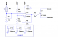
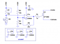
I've got a LM324 OPAMP connected as a Comparator circuit with a LDR. The circuit works well as it is, but I would like to connect a Flash Gun to it.

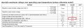
I'm told I need to use the CP106D SCR but have not a clue how to connect it to this circuit.

I've attached the datasheets.

Any help will be appreciated/advice. Many Thanks - JDR04
 

Attachments

Thread Starter

JDR04

Joined May 5, 2011
367
Hi Ron H, thanks for your reply. I've got the flash user manual so I'll try and get more details on the flash for you. In the meantime, its a METZ MECABLITZ 58 AF-1 C DIGITAL. The C is specifying that its for a a Canon EOS model camera.

Thanks again JDR04
 

Thread Starter

JDR04

Joined May 5, 2011
367
I'm also new to electronics. I was told the SCR was best suited to handle the high voltages from the flashgun??? Thanks - JDR04
 

Thread Starter

JDR04

Joined May 5, 2011
367
Ron H, had a look through the specs in the manual. There are no voltages or currents quoted. I could perhaps email support and ask them - how critical is it?

All I can tell you is it needs 4X 1.5V AA batteries. - JDR04
 

Ron H

Joined Apr 14, 2005
7,063
Ron H, had a look through the specs in the manual. There are no voltages or currents quoted. I could perhaps email support and ask them - how critical is it?

All I can tell you is it needs 4X 1.5V AA batteries. - JDR04
I couldn't find a manual online.
What port are you intending to connect the SCR to?
I find it hard to believe that they would not provide a low voltage, low current trigger input.
 

Thread Starter

JDR04

Joined May 5, 2011
367
I cant find any other specs anywhere. The flash only has two ports, one is for an external power pack and the other is to download software updates.

I'm thinking the way to do it is the same way when you taske the flash "off camera" to avoid red eye etc. You have to use a hot shoe connection that either connects to the PC flash sync terminal on the camera or a hot shoe that connects to the cameras hot shoe?

I see a while back you posted a circuit that uses a SCR connected to 2N2222 trannies, could something like this be done?

I dont know if it would help, There are 5 pins at the bottom of the flash gun. Whatever is connected, will have to be connected via some of these pins, I think.

Cheers and thanks for your time - JDR04
 

Thread Starter

JDR04

Joined May 5, 2011
367
I'm led to believe that only two of the pins are required for triggering a flash. In this instant, the other pins are for through the lens metering, zoom control in the flash etc etc. At this stage I'm nopt worried about metering and zoom control.

Can anybody provide clarity or any comments??? Thanks - JDR04
 

Ron H

Joined Apr 14, 2005
7,063
I'll put together a schematic that will use your existing circuit (with some modifications) to drive your SCR, but obviously, I won't guarantee that it will trigger your flash, or not be damaged, or not damage your flash unit.
 

Ron H

Joined Apr 14, 2005
7,063
OK, here it is. Note that the op amp inputs are swapped in order to make the SCR trigger when light increases. If you want it to trigger when light decreases, let us know. You can't do this by simply swapping the inputs.
Also note that the unused op amps are connected in a manner which will keep them from oscillating or upsetting the biasing circuitry.
 

Attachments

panic mode

Joined Oct 10, 2011
4,974
the circuit looks fine. the only thing needed is reference to flash circuit (probably just connect negative terminals if the SCR is part of flash)
 

Thread Starter

JDR04

Joined May 5, 2011
367
Thanks Ron H. I understand most of the circuit but not all. Could somebody explain the function of R6 please.(Is this to set some sort of amplification?)

Just two other points, I will need to power the circuit off a 9V battery so its portable and not 15V. I will also need to have it detect Darkness rather than Lightness (sorry) if that makes any sense. Can this be done by swapping U3 and R5 around??

Thanks a lot for your time and input, it's really appreciated. JDR04
 

Ron H

Joined Apr 14, 2005
7,063
Thanks Ron H. I understand most of the circuit but not all. Could somebody explain the function of R6 please.(Is this to set some sort of amplification?)

Just two other points, I will need to power the circuit off a 9V battery so its portable and not 15V. I will also need to have it detect Darkness rather than Lightness (sorry) if that makes any sense. Can this be done by swapping U3 and R5 around??

Thanks a lot for your time and input, it's really appreciated. JDR04
R6 adds hysteresis. I habitually add it to comparator circuits, to prevent jitter and/or bounce and/or oscillation at the switch point. In this case, it is probably not necessary. The SCR will either switch or it won't, and once on, you have to interrupt the current to get it to turn off, i.e., the gate voltage no longer matters.
You are correct about swapping the LDR and the pot.:)
 

Attachments

donpetru

Joined Nov 14, 2008
185
Concerning electronic diagram posted above,

CP106D has positive peak gate current about 0,2A, what is too much for the LM324 operational amplifier. So, I do not recommend the above electronic diagram.

But why are you required to use a thyristor? Is much easier is to use a MOSFET.
 

donpetru

Joined Nov 14, 2008
185
The idea is, to put SCR ala the moving, you need something more than 20mA as a support of the LM324 operational amplifier. That I wanted to point out or draw attention.

Later edit: Note that since the beginning of the datasheet is wrong: Max IGT of 200 μA

Look below:
 

Attachments

Top