How to connect a CT-sensor to an Arduino Giga?

Thread Starter

Rensieboy223

Joined Feb 3, 2024
88
Almost there:
1. If you calculate for 100A rms you can never measure more than 100A rms, which you may wish to do in cases of overload.
If 100A rms is the maximum you could ever need to measure, even in overload conditions you are OK.
2. The AD8418 has a gain of 20. So you need to scale the reference voltage by 20.
3. The burden resistor is the load on the transformer secondary, so it goes across the transformer terminals.

I always aim for 1V rms on the processor pin, at my reference current. That gives 16% headroom for overloads, and makes the maths simple for the burden resistor calculations. It also lets me reuse all my software that I have written for AC current inputs, as I just have to scale the result to the reference current.
So then the calculation would be:

Output CT-sensor: 100A/2500= 0,04A
Gain of 20 at the amplifier, so 50mV from the CT-sensor to the amplifier right?
So how do i go from here?
 
Last edited:

Thread Starter

Rensieboy223

Joined Feb 3, 2024
88
Yes. That's about the value I would expect.
I usually use CTs with 1A secondary, and they need a burden of 50mΩ

I presume you also need to sense the voltage as well as the current.
If so, this might be useful:
https://www.micro-transformer.com/2ma-2ma-voltage-transformer-ZMPT101B.html
But the voltage that's going to the CT-sensor is 3,3v right? So isn't it then:
3,3v-0,05/0,04?

And does your setup work with the 50miliohm burden?

And do i need to add extra diodes or capacitors somewhere to ensure Safety?
 

Ian0

Joined Aug 7, 2020
13,286
But the voltage that's going to the CT-sensor is 3,3v right? So isn't it then:
3,3v-0,05/0,04?

And does your setup work with the 50miliohm burden?

And do i need to add extra diodes or capacitors somewhere to ensure Safety?
It's safe the way it is. A diode as per my D3 will keep the input voltage within the common mode range.

The input at the processor is a steady 1.65V with no current through the CT.
With 100A through the CT the input to the processor will be a sinewave with a positive peak at 1.65+1.41V and a negative peak at 1.65-1.41V
 

Thread Starter

Rensieboy223

Joined Feb 3, 2024
88
It's safe the way it is. A diode as per my D3 will keep the input voltage within the common mode range.

The input at the processor is a steady 1.65V with no current through the CT.
With 100A through the CT the input to the processor will be a sinewave with a positive peak at 1.65+1.41V and a negative peak at 1.65-1.41V
Okay thanks man,
But can this AD8418A handle 400V going through the cabels, or doesn't that matter?

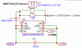
I got i now like this, let me know if everything is okay:
1707644126931.png

And also, how to program the arduino right now if my voltage is 1V RMS?
 
Last edited:

Ian0

Joined Aug 7, 2020
13,286
Okay thanks man,
But can this AD8418A handle 400V going through the cabels, or doesn't that matter?

I got i now like this, let me know if everything is okay:
View attachment 314959

And also, how to program the arduino right now if my voltage is 1V RMS?
How will it know what voltage is on the cables? It is separated by one or two layers of cable insulation and the plastic case of the CT itself. That combination will have a breakdown voltage of >5kV.
 

Thread Starter

Rensieboy223

Joined Feb 3, 2024
88
How will it know what voltage is on the cables? It is separated by one or two layers of cable insulation and the plastic case of the CT itself. That combination will have a breakdown voltage of >5kV.
Okay clear,

The rest is good for fabrication?
And can i add a LED for power conformation?
 

Thread Starter

Rensieboy223

Joined Feb 3, 2024
88

Ian0

Joined Aug 7, 2020
13,286
It's exactly the same type of current transformer. You can connect it with either of my two circuits in Post #6, just the same as the other current transformers.
You can't simply connect it to 3.3V and the input, because:
a) it needs a burden resistor
b) the output is still a sinewave and it will then be centred on 3.3V so you won't be able to measure the top part of it.
(similarly, you can't just connect it to input and 0V as you would lose the bottom half of the signal)
c) you need to protect the input against overvoltage during periods of excess current.
 

Thread Starter

Rensieboy223

Joined Feb 3, 2024
88
It's exactly the same type of current transformer. You can connect it with either of my two circuits in Post #6, just the same as the other current transformers.
You can't simply connect it to 3.3V and the input, because:
a) it needs a burden resistor
b) the output is still a sinewave and it will then be centred on 3.3V so you won't be able to measure the top part of it.
(similarly, you can't just connect it to input and 0V as you would lose the bottom half of the signal)
c) you need to protect the input against overvoltage during periods of excess current.
Clear to me man,

So the setup I made is good in the schematic? Post #27?
 

Thread Starter

Rensieboy223

Joined Feb 3, 2024
88
https://en.wikipedia.org/wiki/Root_mean_square
Unfortunately, current waveforms are rarely sinusoidal, so you have no alternative but to do it the difficult way!
However, if you need to know the power, but don't need to know the current you can avoid the square root.
Well i need the current to calculate the power in KW.

But for my own vision, the Amplifier will give voltage around 1v to the Arduino linear to it's measured current right. And i have to put that to RMS to know the exact current right?
 
Top