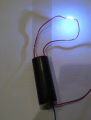
How to check this 400kV Boost Power Module's voltage and frequency?

shortbus

Joined Sep 30, 2009
10,049
It's easy to add a start if its a suitable V and F.
Well may be easy for you but not the rest of the world. I have an old lift start Tig that I tried many ways shown on the internet to make into a HF start. None of them worked. The words "high frequency mean that the HF supply box you make has to be an AC output. Then you need to make a HF transfer coil to put the HF HV into the low voltage DC supply coming out of the welder. This transfer coil is the problem. I couldn't find any real information on how they were made, but none of the ones I tried would work.

In the end I just bought one that has AC(for welding aluminum) and DC for welding steel. I got a very good one, an inverter type, for a very good price. If your thinking of this as an add on to a buzz box, tombstone type stick welder you still need a way to control current and gas flow with a foot pedal. And make it DC if your going to weld steel.

Here is a link to an add on HF start and it's owners manual -
https://www.arcpig.com/index.html
https://www.arcpig.com/arc_pig_user_manual.pdf
 

shortbus

Joined Sep 30, 2009
10,049
@LAOADAM, Here is a DIY HF start that was in Make Magazine, it wasn't around when I tried to make one. But be sure to read the part near the bottom of the page where it says "notes". This applies to any inverter welder because they are internally mostly the same circuit in a different box.
" Notes
If you're thinking of building this and adding it on to the cheap (non-hf start) TIG from Harbor Freight, don't. Unless you can figure a fool proof way to keep the high voltage and RF out of the Harbor Freight TIG, you'll toast it."

https://www.dudley.nu/projects/hfstart/
 
@shortbus

I liked reading the website and manual for the ArcPig. Although, I did do one weld with a stick MIG and TIG welder and did very well. I really had no reason to use the one at work. My TIG lesson did not use filler rod. We had a huge welder that did not do aluminum. They sold it and bought a small MIG welder. Our director put a lid on who can use the welder, but before he did I was offered a shot at welding. With a lot of stuff, set ups are the real problem.

the one thing, I did do which was one of my famous "kill-me-quicks" as they were called.
1) I opened like a 30 A 208 outlet and connected the welder with wirenuts for a low current job
2) A valve controller was being worked on by me and in order to use the vacuum system, I took a "switch per outlet" outlet strip
and poked the wires to the valve in the receptacles. It only had to work for a day. It had to be done quickly.


machine shop: Same deal. Initially I was either set up, then set=ups were looked at then I was able to set-up others.
One guy got upset when I set up a mechanical engineering student to drill about 100 1/4" holes in a piece of Molybdenum.
I had purchased a ball end mill for the job and the shop "babysitter' I don;t think knew how to use auto-feed.
We did have a digital readout for X and Y on the mill. The "babysitter" really got upset, but he had no leg to stand on.

I think because I could silver solder the best of everyone and I could glass blow, welding was surprisingly easy. The auto-dimming helmets were essential. My father had a buzz box.
 
Last edited:

Thread Starter

LAOADAM

Joined Nov 21, 2018
956
Well may be easy for you but not the rest of the world. I have an old lift start Tig that I tried many ways shown on the internet to make into a HF start. None of them worked. The words "high frequency mean that the HF supply box you make has to be an AC output. Then you need to make a HF transfer coil to put the HF HV into the low voltage DC supply coming out of the welder. This transfer coil is the problem. I couldn't find any real information on how they were made, but none of the ones I tried would work.

In the end I just bought one that has AC(for welding aluminum) and DC for welding steel. I got a very good one, an inverter type, for a very good price. If your thinking of this as an add on to a buzz box, tombstone type stick welder you still need a way to control current and gas flow with a foot pedal. And make it DC if your going to weld steel.

Here is a link to an add on HF start and it's owners manual -
https://www.arcpig.com/index.html
https://www.arcpig.com/arc_pig_user_manual.pdf
Thanks.
I never did any work on that, but searched out there are many board can be used, may be the fact is not that?
Did you try this solution:

pp04.PNG

https://www.aliexpress.com/item/100...xp_id=ad8b5e20-09c9-43b0-a005-d8a88fed5eba-12

https://www.aliexpress.com/item/1005002253989349.html?spm=a2g0o.cart.0.0.39823c00d9NXl3&mp=1
 

Thread Starter

LAOADAM

Joined Nov 21, 2018
956
@LAOADAM, Here is a DIY HF start that was in Make Magazine, it wasn't around when I tried to make one. But be sure to read the part near the bottom of the page where it says "notes". This applies to any inverter welder because they are internally mostly the same circuit in a different box.
" Notes
If you're thinking of building this and adding it on to the cheap (non-hf start) TIG from Harbor Freight, don't. Unless you can figure a fool proof way to keep the high voltage and RF out of the Harbor Freight TIG, you'll toast it."

https://www.dudley.nu/projects/hfstart/
Thanks.
I'll use the solution in #25, I test the high voltage only because my order doesn't coming yet, also I'd like to practice more.
 

Thread Starter

LAOADAM

Joined Nov 21, 2018
956
@shortbus

I liked reading the website and manual for the ArcPig. Although, I did do one weld with a stick MIG and TIG welder and did very well. I really had no reason to use the one at work. My TIG lesson did not use filler rod. We had a huge welder that did not do aluminum. They sold it and bought a small MIG welder. Our director put a lid on who can use the welder, but before he did I was offered a shot at welding. With a lot of stuff, set ups are the real problem.

the one thing, I did do which was one of my famous "kill-me-quicks" as they were called.
1) I opened like a 30 A 208 outlet and connected the welder with wirenuts for a low current job
2) A valve controller was being worked on by me and in order to use the vacuum system, I took a "switch per outlet" outlet strip
and poked the wires to the valve in the receptacles. It only had to work for a day. It had to be done quickly.


machine shop: Same deal. Initially I was either set up, then set=ups were looked at then I was able to set-up others.
One guy got upset when I set up a mechanical engineering student to drill about 100 1/4" holes in a piece of Molybdenum.
I had purchased a ball end mill for the job and the shop "babysitter' I don;t think knew how to use auto-feed.
We did have a digital readout for X and Y on the mill. The "babysitter" really got upset, but he had no leg to stand on.

I think because I could silver solder the best of everyone and I could glass blow, welding was surprisingly easy. The auto-dimming helmets were essential. My father had a buzz box.
Thanks.
 

shortbus

Joined Sep 30, 2009
10,049
Thanks.
I'll use the solution in #25, I test the high voltage only because my order doesn't coming yet, also I'd like to practice more.
While those are or look like replacements for an existing Tig welder, you still have to figure out how to keep the hF out of the rest of your welder circuit. Since the HF goes into the welder output cable it will go both ways in thaat cable, to the electrode/torch AND back into the welding transformer. There is something, that I don't know what it is, that keeps it from going into the rest of the welder circuit. Without that part of the puzzle you can ruin your welder, like it says in that note from the DIY circuit.
 

ronsimpson

Joined Oct 7, 2019
4,771
how to measure its voltage and frequency?
Frequency, I don't know what tools you have. I would use a scope and a piece of wire. Loop the wire one (or more) turns around the input end of the HV supply. There should be enough voltage on one turn of wire to measure frequency. You might have to move the wire up / down a little to find the right spot. Probably just lay a scope probe near the supply.
1624108869750.png
There is a formula (ask google) for spark distance in air. See above example of spark distance. This is not accurate but will give you some idea.

The supply does not look like 400,000. volts. I have made many HV supplies and the supply does not look like 400kv. But look at the length of the spark and I now think it is HIGH VOLTAGE.
 

Thread Starter

LAOADAM

Joined Nov 21, 2018
956
Frequency, I don't know what tools you have. I would use a scope and a piece of wire. Loop the wire one (or more) turns around the input end of the HV supply. There should be enough voltage on one turn of wire to measure frequency. You might have to move the wire up / down a little to find the right spot. Probably just lay a scope probe near the supply.
View attachment 241658
There is a formula (ask google) for spark distance in air. See above example of spark distance. This is not accurate but will give you some idea.

The supply does not look like 400,000. volts. I have made many HV supplies and the supply does not look like 400kv. But look at the length of the spark and I now think it is HIGH VOLTAGE.
Thanks.
I'll test this out.
 
Top