 Facebook
 Google
 GitHub
 Linkedin
Hello everybody,
I would like some advices on balanced matching circuit utilisation. Today, my goal has to use in series a MRF136Y and a D1008UK with a wide-band working (from 40 MHz to 400 MHz) but I obtain some problems of impedance between.
After the MRF136Y, I use a transformer to obtain an unbalanced 50 Ohms output and after, I use a guanella transformer to attack the D1008UK but I think that it exist an easier method that my method. But which ?

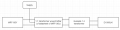
Secondly, I don't understand the input stage (balanced matching network ?) of the D1008UK application note shematic (cf picture), I'm looking for some explications.

Have a good day!
Joss
I would like some advices on balanced matching circuit utilisation. Today, my goal has to use in series a MRF136Y and a D1008UK with a wide-band working (from 40 MHz to 400 MHz) but I obtain some problems of impedance between.
After the MRF136Y, I use a transformer to obtain an unbalanced 50 Ohms output and after, I use a guanella transformer to attack the D1008UK but I think that it exist an easier method that my method. But which ?
Secondly, I don't understand the input stage (balanced matching network ?) of the D1008UK application note shematic (cf picture), I'm looking for some explications.
Have a good day!
Joss
Attachments
-
 15.8 KB Views: 5


