Facebook
 Google
 GitHub
 Linkedin
Hello! I'm a college student in electronics engineering and I'm struggling in our project which is a Mini Audio Amplifier.
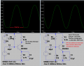
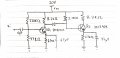
I would like to ask for help on how to add a buffer stage for my mini audio amplifier project. The instruction for this project is to create a 2 stage amplifier that will produce a voltage gain of at least 50. I have made a two-stage amplifier without a buffer and the output was very noisy. I figured that a buffer is important for an audio amplifier.
The amplifier that I previously made has a Voltage Divider Bias Configuration as the first stage and an Emitter follower as the second stage. The output was not very good. It might have been because my transistor was overheated by the soldering iron but I think it might be because the circuit is not very good as well.
Also, this amplifier will be connected to a 4 ohm and 5W speaker.
The photo attached here was my previous amplifier.
I would appreciate suggestions and ideas for this. Thank you very much!
Attachments
-
 269 KB Views: 33