 Facebook
 Google
 GitHub
 Linkedin
Hi all,
Not sure if this is the correct forum but it's power related so the closest I could find.
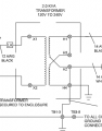
If you look at the attached image of a transformer it states 120V to 240V, can somebody explain how you would get 240V out if the output taps are directly across one winding?
I can only assume that if the other winding was connected this would give 480V out (assuming the windings are matched). Is that correct or am i getting my knickers in a twist?
Cheers
Mitch
Not sure if this is the correct forum but it's power related so the closest I could find.
If you look at the attached image of a transformer it states 120V to 240V, can somebody explain how you would get 240V out if the output taps are directly across one winding?
I can only assume that if the other winding was connected this would give 480V out (assuming the windings are matched). Is that correct or am i getting my knickers in a twist?
Cheers
Mitch
Attachments
-
 19.8 KB Views: 27

")


