How does this comparator circuit work?

Thread Starter

Blue_Electronx

Joined Jun 10, 2019
112
Hi,

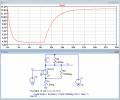
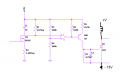
I'm trying to understand the circuit below. I know the comparator voltage reference is 13/2 = 6.5V and is set at the inverting input of the comparator. However, my confusion is about the input voltage in the non-inverting pin. Is it affected by capacitor C1? When the FET is turned on, R1 and R2 form a resistor divider, but how is it affected by C1?

NOTE: FET M1 is not actually a FET. It's an inverter like this one.


ericgibbs

Joined Jan 29, 2010
18,766
hi,
At rest, C1 is not charged, voltage across it is zero.
When pulsed, the lower end of C1 is pulled down to 13v * (1.2/(2.5+1.2) = ~ 4.2V
C1 will charge exponentially charge to approx 13V-4.2V = 8.7v, it could be just a noise filter or need to create a slow edge for the comp.
E

EDIT:

LTS plot of the C1 voltage, corrected.
 

Attachments

Last edited:

MisterBill2

Joined Jan 23, 2018
18,167
The ultimate effect of the C1 capacitor will be for the comparator to oscillate as the positive input voltage slowly passes the inverting input voltage. Also, unless that comparator is powered, nothing at all will happen. One more thing is that I would consider a 4007 CD4007? to be an inverter. The data sheet calls it an analog switch, and so would I.
 

crutschow

Joined Mar 14, 2008
34,280
I see no reason for Q1, as the comparator can just drive the SCR directly if the comparator inputs are reversed to keep the signal polarity at the SCR input the same.
 

ebeowulf17

Joined Aug 12, 2014
3,307
I see no reason for Q1, as the comparator can just drive the SCR directly if the comparator inputs are reversed to keep the signal polarity at the SCR input the same.
Is that still true if the comparator has an open collector output, as many do? Wouldn't it be unable to source current like Q1 does in that case?
 

MisterBill2

Joined Jan 23, 2018
18,167
Is that still true if the comparator has an open collector output, as many do? Wouldn't it be unable to source current like Q1 does in that case?
Because this comparator also shows no power connections we can presume that it is a theoretical comparator or a simulation comparator and so does not need a power connection. There are many different kinds, the LM339 has no pullup, only open collector NPN output, while the LM311 has both collector and emitter available. But because no type was specified it does not matter..
 

Thread Starter

Blue_Electronx

Joined Jun 10, 2019
112
The comparator used is the LMC6772. It's a low power comparator. Perhaps that's why a PNP transistor is used? Do you think that just leaving R6 and R7 would work?
 

ericgibbs

Joined Jan 29, 2010
18,766
hi Blue,
For the cost a PNP general purpose transistor I would use the original circuit.
The LMC is open Drain output and say the SCR requires 10mA of trigger current, means that the value of R6 would have to be reduced.... etc

Do you have details of the SCR .?
E
 

ericgibbs

Joined Jan 29, 2010
18,766
hi,
That could be Gated On using a resistor pull up resistor to +Vdd.
If you omit the PNP, as already pointed out you must change the comp inputs over in order to keep the correct gate sense.
E

scr1.PNG
 

crutschow

Joined Mar 14, 2008
34,280
The comparator used is the LMC6772. It's a low power comparator. Perhaps that's why a PNP transistor is used? Do you think that just leaving R6 and R7 would work?
The S6S2 requires a minimum of 50μA to trigger
The LMC6772 output is rated for a 5mA (sink) load, so will have no problem driving the SCR.

But you would need to leave R5 and R7 (omitting R6 and the transistor) as well as reversing the inputs to the comparator.
 

Thread Starter

Blue_Electronx

Joined Jun 10, 2019
112
Hi,

In the circuit attached below, what if the cathode of the SCR is referenced to - 13V, while the comparator is referenced to common or 0V, that is, single supply? Would the PNP still be needed? The circuit has dual power supply 13V, 0V, -13V.
 

Attachments

Alec_t

Joined Sep 17, 2013
14,280
If the PNP were not there, then because the comparator output only swings between 0V and +13V it could never be below the turn-on voltage of the SCR.
 
Top