 Facebook
 Google
 GitHub
 Linkedin
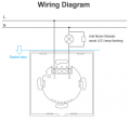
So, I just bought a Sonoff T2 smart switch. Basically it replaces a normal light switch with a smart switch that can be flicked on and off remotely over WiFi. This is the two-wire model, since in this house the switch boxes don't have any Neutral or Earth wires - there's just the Live wire going into the switch box (coming from the main circuit breaker), and the Live wire going out of the switch box (going to the light fixture).
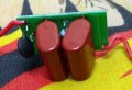
The switch has no built-in power supply (battery), so it somehow draws current from the mains to power itself. Part of the installation involved putting an "anti-flicker" device in parallel with the lamp. I've disassembled this device and it's just a pair of polyester capacitors across the lamp's live and neutral wires.
So my theory for how the switch powers itself when the light is OFF is that with the switch and anti-flicker device all in series with each other across mains voltage, a small current flows through the capacitors in the anti-flicker box and the switch, and it's able to harvest that. So far it's simple.
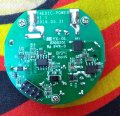
What I can't understand is how the switch powers itself when the light is ON, since the relay clicks and allows full current to the light. If the two terminals of the smart switch are essentially shorted together via the relay, how can the switch draw any power? This switch can handle up to 15 Amps. I didn't see any low-resistance shunts in the internal circuitry, I was able to identify a bridge rectifier, transformer, large electrolytic capacitor and various diodes, transistors and ICs.
Can anyone think of a way the switch is harvesting power with lamp on? I've attached pics of the wiring diagram and switch's power board and anti-flicker device. The power board stacks onto the logic board via the 8-pin connector.
The switch has no built-in power supply (battery), so it somehow draws current from the mains to power itself. Part of the installation involved putting an "anti-flicker" device in parallel with the lamp. I've disassembled this device and it's just a pair of polyester capacitors across the lamp's live and neutral wires.
So my theory for how the switch powers itself when the light is OFF is that with the switch and anti-flicker device all in series with each other across mains voltage, a small current flows through the capacitors in the anti-flicker box and the switch, and it's able to harvest that. So far it's simple.
What I can't understand is how the switch powers itself when the light is ON, since the relay clicks and allows full current to the light. If the two terminals of the smart switch are essentially shorted together via the relay, how can the switch draw any power? This switch can handle up to 15 Amps. I didn't see any low-resistance shunts in the internal circuitry, I was able to identify a bridge rectifier, transformer, large electrolytic capacitor and various diodes, transistors and ICs.
Can anyone think of a way the switch is harvesting power with lamp on? I've attached pics of the wiring diagram and switch's power board and anti-flicker device. The power board stacks onto the logic board via the 8-pin connector.
Attachments
-
 39.3 KB Views: 84
 -
 2.7 MB Views: 79
 -
 1.5 MB Views: 73
 -
 2.7 MB Views: 66
 -
 987 KB Views: 66


