
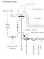
In this scenario, there is a 12v latching solenoid valve which lets water run through a tap when a hand is placed under the sensor.

We have designed a separate circuit to connect to this valve and flush the tap at our command (this is an IoT project using GPIO pins on a microcontroller). This is our circuit (I assume the tap has a similar configuration):

To close the valve, 12v must be applied for about 0.5s, and to open, -12v must be applied for about 0.5s. In between, the valve remembers its position (as it is latching).
Both work separately but, without plumbing a new valve in, can we connect this new circuit directly to control the same valve?
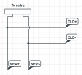
The new connection will look something like this:

One problem I foresee is that there will be a short circuit on the opposing circuit when attempting to control the valve (as it is held at the same potential).
We cannot modify the original sensor tap, but we can put some intermediary circuit before the wires reach the valve.
One thought I had was to place in 4 resistors, but that might prevent enough current getting to the valve, right? (The valve draws about 250mA on activation.)
Many thanks for anyone who can help me solve this one!
We have designed a separate circuit to connect to this valve and flush the tap at our command (this is an IoT project using GPIO pins on a microcontroller). This is our circuit (I assume the tap has a similar configuration):
To close the valve, 12v must be applied for about 0.5s, and to open, -12v must be applied for about 0.5s. In between, the valve remembers its position (as it is latching).
Both work separately but, without plumbing a new valve in, can we connect this new circuit directly to control the same valve?
The new connection will look something like this:
One problem I foresee is that there will be a short circuit on the opposing circuit when attempting to control the valve (as it is held at the same potential).
We cannot modify the original sensor tap, but we can put some intermediary circuit before the wires reach the valve.
One thought I had was to place in 4 resistors, but that might prevent enough current getting to the valve, right? (The valve draws about 250mA on activation.)
Many thanks for anyone who can help me solve this one!
Attachments
-
 107.5 KB Views: 4
 -
 481.7 KB Views: 3
 -
 26.1 KB Views: 3


