
 Facebook
 Google
 GitHub
 Linkedin
I am trying to understand small signal equivalent circuits, I am having some trouble understanding this diagram:
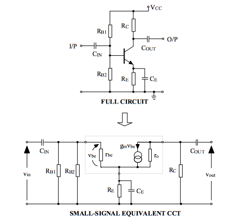
The RB1 and RB2 resistors end up in parallel on the SSEM circuit. Is this because we set the DC voltages=0 for SSEM? (And so, the nodes with same voltage are connected?)
What slightly confuses me is that the input voltage will now be across two resistors compared to the macro model where its across RB2 only. Can someone explain this to me?
The RB1 and RB2 resistors end up in parallel on the SSEM circuit. Is this because we set the DC voltages=0 for SSEM? (And so, the nodes with same voltage are connected?)
What slightly confuses me is that the input voltage will now be across two resistors compared to the macro model where its across RB2 only. Can someone explain this to me?






