How do I properly remove solder from the through-holes after desoldering pin headers on my Arduino?

Thread Starter

denni

Joined Jul 18, 2023
65
Hey folks,

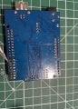
I was trying to desolder some female pin headers from my Arduino (upper left area of the board in the pictures, look where the tweezers points to). I managed to successfully remove the headers by bridging the solder across the holes while using tweezers to pull the pins from the other side.

After removing the headers, I applied solder wick to clean up the remaining solder. I removed most of it, but some residue remained inside the through-holes. I couldn’t completely clear the holes, which made reinserting the pin headers difficult because the holes weren’t empty.

So, I took a very thin soldering iron tip(the T-IS tip: look the pictures down below) , cranked the temperature up to 420°C, and tried to force the iron into the holes while the solder melted, hoping the solder would stick to the tip. It worked after some attempts, but I think I may have damaged the pads.
IMG_5737.jpeg
IMG_5735.jpg
IMG_5736.jpeg

And here is the T-IS tip:
1725983960066.png

Here’s what I noticed:

  • The solder doesn’t seem to stick to the damaged pads anymore, regardless of the temperature.
  • In one of the pictures, I pointed the tweezers at the ring of one hole, which should be the same color as the solder, but it think it is damaged.
  • I tested for continuity on the outer ring, and there’s none, which I think means the pad is no longer conductive.

Despite this, I was able to reinstall the pin headers, and some solder still managed to stick, but I’m kinda concerned about the damaged pads.

TLDR, My questions:

  1. What’s the best way to remove solder residue inside the through-holes without damaging the pads, especially if solder wick doesn’t work effectively?
  2. Can the pads be repaired if they no longer conduct solder properly? I mean does it matter to be repaired , as long as the pin pass current there is no need to repair them no ? But still I want to know how to prevent this ?

Thanks
 

Attachments

dl324

Joined Mar 30, 2015
18,266
After removing the headers, I applied solder wick to clean up the remaining solder.
Solder wick should have worked. If you don't have a solder sucker, you could melt the solder and use a wet toothpick to clear solder from the hole.

Regarding damage. If the board is only double sided, you can solder jumpers to any traces that get disconnected from pads. If the board has more than 2 layers, repair is more involved if you pulled out any of the plating through the holes.
 

panic mode

Joined Oct 10, 2011
4,929
solding is a skill and like anything else it requires studying and practice... using too much heat or force or bad timing can result in board damage.

copper is only glued to the board so too much heat softens/disolves the glue. this is why there is a temperature regulation on just about every soldering tool. there are also low melting point solders. multilayer boards tend to draw heat away a lot more than simple 1 or 2 layer boards. this leads to temptation to use higher than necessary temperature, force or both. repair can be simple or involved. usually problem is small size of the area to work on, hence reason to use magnification. removing multi-pin THT parts like pin headers is difficult without right tools. in that case it is better and easier to destroy the component then desolder pins individually. of course destruction also need to be done carefully to not put stress on the board because that is part to be reused.

as for repair, there are number of ways and plenty of instructions/videos. for non-plated through repair for someone with limited experience try something like this:
https://www.instructables.com/How-to-Repair-Damaged-Printed-Circuit-Board-Pads/

same can be done to both sides of the board and then plating through can be accomplished by using rivets. note that properly used rivets will still allow insertion of THT part but it will only connect outer layers. any success to connect inner layers is pure luck and most likely contact will be rather poor.
rivet system uses punch with replaceable tips for different sizes. punch need to be set correctly: to much force will damage the board and lift copper even on a brand new board (for example CNC milled board). too little and rivet will not be formed correctly and contact if any will be poor. this can be remedied by sodering both sides. i prefer to solder them anyway.
https://www.mouser.de/c/electromechanical/hardware/circuit-board-hardware-pcb/?q=eyelet

the rivets diameter need to match the hole size and length need to be matched correctly to board thickness.

video here shows milled PCB and inserting rivets but they did not use an anvil (small block of steel). without anvil results will be boor at best.
https://forum.arduino.cc/t/cheap-pcb-eyelets-rivets-and-tools-for-diy-vias/849547/6

another DIY option is to insert strand throug the hole and solder it to both sides. this too need to be done carefully, ends need to be bent to reduce risk of moving that strand while soldering component.
 

panic mode

Joined Oct 10, 2011
4,929
as long as the pin pass current there is no need to repair them no ? But still I want to know how to prevent this ?
not exactly... pads provide electrical connectivity as well as mechanical support of the part. if you have a 10 pin part but only one pad is ruined, rest of the pads should be able to provide mechanical support, specially for component that does not get exposed to further abuse (connectors). but if you damage 7 pads, there is no hope of providing mechanical stability by remaining three pads. in this case you may have no choice but to superglue the connector to prevent movement.
 

MrChips

Joined Oct 2, 2009
34,698
As panic says, it takes practice.
What works for me, I add fresh Sn/Pb solder with rosin to the pad and then use a solder sucker to suck the solder away.
The trick with any PCB rework, is to not use more heat and time necessary to get the job done, otherwise you risk lifting the pads and tracks off the board.
 

panic mode

Joined Oct 10, 2011
4,929
yup... that is pretty universal experience. so it is better to practice on some scrap board before working on one you need repaired.

there is number of ways to get things out and each has pitfalls. desoldering simple THT resistor can burn fingers and since most of the time leads are bent before soldering, enough of solder will remain to keep the part in place. using tool to break the bond of nearly free pin can lead to pad or plating damage. using tool to pull resistor while solder is melted can also be problematic of not done carefully. for example if solder is not melted entirely, one can rip the pad or plating. sometimes there is not enough solder to be removed. so one may want to add more to create bubble of liquid solder and then use solder sucker etc. once the molten solder is in motion, it can help pull remainder and leave surfaces nearly dry.
prolonged heat is likely to damage both parts and the board. so when working on board with heavy copper or multilayer, it helps to use heater to warm up the board area of interest... not enough to desolder, but to make it warm just like with soldering (preheat). this makes work easier. fine tips are great for delivering heat to small area but they are not stable, they cool of easy. i like to work with chisel tip. using the flat side can deliver enough of heat without need to toast the part.
 
Last edited:

Ian0

Joined Aug 7, 2020
13,112
Use the solder sucker. Heat the pad with the soldering iron, not too hot or the pad will peel off, but wait a couple of seconds for the heat to flow all the way through to the underside of the board before using the solder sucker.
Also worth a go if you have it is compressed air.
 

bassbindevil

Joined Jan 23, 2014
922
Solder sucker from the opposite side of the board, or insert a stainless steel needle while the solder is liquid. You may get away with using a fine drill bit to clean out most of the remaining solder (HSS numbered drill in a pin vise); the hole left by the needle will tend to guide the drill down the centre so you don't damage the through-plating. Or, if there's only one hole that's not clear, insert your new component while the solder in that hole is liquid.
 

KeithWalker

Joined Jul 10, 2017
3,604
I find spring loaded solder suckers are a bit rough on the board and difficult to control, as well as stressing my arthritic thumbs.
IanO mentioned compressed air. That is what I use very successfully on even the most delicate of PC boards. I melt the solder and then use a can of compressed air with a fine tube to direct it on the hole. Just be careful of where the solder is going to be blown.
 

Ya’akov

Joined Jan 27, 2019
10,226
Particularly for a neophyte, I would recommend using a low melting point alloy or “removal alloy” to make removing the component easier. This is the one I use, and it’s been very good. There are others but without testing the only one I think I would trust is the QuickChip offering. It may seem expensive but you will use so little on each job you’ll find it lasting a long time.

The idea is that by introducing a tiny amount of the alloy to the existing solder, the melting point drops low enough for all the pins to be free at the same time. Without a vacuum desoldering tool, 40-pin headers are a daunting desoldering job, even for an experienced person.

The low melt alloy will literally allow the part to fall off the board. There are, of course, caveats:

  1. You only need a tiny amount. If you apply to much you will have a mess to clean up.

  2. You must clean up both the pads (using solder wick) and the iron tip. Do not use the iron on anything else until you have cleaned off the residue and re-tinned the tip.

  3. Avoid contaminating pads other than the ones directly involved.

Some tips:

  • Apply small amount of leaded solder to the pads involved to start. While a eutectic alloy (Sn63/Pb37) is best for making solder joints, Sn60/Pb40 is best for this application because of its superior wetting. That is, it will more readily alloy with existing metals. You can use the eutectic solder, though, and it will still work.

  • Mount the board in a vice or some other way such that it is off the work surface at a height sufficient for the part to come completely free of the board—because gravity is your friend and besides having the part fall free is very satisfying. If you can’t do this, you will have to lift the PCB once all pins are free.
Good luck, what you are doing is one of the hardest desoldering jobs short of LEDs on aluminum PCBs or things mounted over huge copper floods intended to be heat sinks. Take your time, be deliberate and careful, and remember to let things cool down if you’ve been struggling with them for a while, and you will find this is just a matter of knowledge and a little experience.
 

MisterBill2

Joined Jan 23, 2018
27,312
One trick not mentioned yet is to use a "solder sucker" that has a squeeze bulb to blow the solder out of the hole after the solder is melted. That first blast of very hot air will not cool the solder, and so it is more effective.
AND understand that heating the copper ALWAYS weakens the bond to the board material, and so only use the minimum heat that works.
 

panic mode

Joined Oct 10, 2011
4,929
conventional solder suckers tend to have a pretty good kick... the bulb version should be much gentler on PCB and pose less demand on holder in terms of how firmly it is held.
 

MisterBill2

Joined Jan 23, 2018
27,312
conventional solder suckers tend to have a pretty good kick... the bulb version should be much gentler on PCB and pose less demand on holder in terms of how firmly it is held.
That is correct, IN ADDITION to the bulb type being able to blow solder out of the hole.
Another benefit of the variety that adds the bulb mechanism to the soldering heater is the reduction of static charges generated by the plastic sucking mechanism of some common solder suckers.
 

MaxHeadRoom

Joined Jul 18, 2013
30,593
I have the both versions that each have a vacuum type action, the bulb type is the bulb-squeeze type with a mains heated tip.
Both work reasonably well.


1726072601921.png
1726072686439.png
 

SamR

Joined Mar 19, 2019
5,473
One method not mentioned is the melt and thump move. Melt the solder and quickly and smartly tap the board against the bench and let inertia do the work. Using a bit of paste flux helps if you have it and I prefer the solder wick route. But in a pinch the melt and thump works but sometimes needs to be followed up with a drill bit and pin vise to thoroughly open the hole. My preferred method is the vacuum pump desoldered way. Not the suckit tubes or rubber bulbs but the full vacuum pumped desoldering irons.
 
Top