How do I make a current source using a zener diode and transistor?

Thread Starter

skymin0202

Joined Feb 11, 2019
15
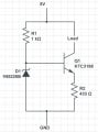
Here's the LTspice simulation of the circuit.
I didn't have models for the devices you bought but the results shouldn't be that different with your devices.
Notice that the current varies less than 0.05% as sensor resistance varies from 6Ω to 400Ω

View attachment 170089

Actually I changed the supply voltage to 5V and the voltage on the zener diode will be 3.3V. If possible, would you please check if it works too??
 

dl324

Joined Mar 30, 2015
18,339
Thank you for your answer. But what resistance would be suitable for R1? Any suggestion? or is there an equation for R1?
I'd operate the zener at Izt, that's the current where Vz is valid. Data from OnSemi datasheet:
upload_2019-2-13_18-51-23.png

For the diode you bought, that would be 20mA.

\( \small R = \frac{V}{I} = \frac{10V-5.1V}{20mA}=245\Omega \)

The closest 5% value is 240 ohms.

If your supply voltage is stable, you could use a lower current.
 

Thread Starter

skymin0202

Joined Feb 11, 2019
15
I'd operate the zener at Izt, that's the current where Vz is valid. Data from OnSemi datasheet:
View attachment 170133

For the diode you bought, that would be 20mA.

\( \small R = \frac{V}{I} = \frac{10V-5.1V}{20mA}=245\Omega \)

The closest 5% value is 240 ohms.

If your supply voltage is stable, you could use a lower current.

hmm... What I did is this.

I thought R1 must supply enough current to bias both the zener and transistor. The transistor has a current gain of 70, then it needs a base current of 6mA/70 = 0.0857 mA. For good voltage regulation, the zener should pass a similar current, so R1 needs to pass about 0.0857 mA. The voltage across R1 will be supply voltage minus the zener voltage. And applying Ohm's Law, (10V-5.1V)/(0.0857*2) = 28588 ohms.

It's quite different from what you did. Which one do you think is right?
 

MrAl

Joined Jun 17, 2014
13,711
hmm... What I did is this.

I thought R1 must supply enough current to bias both the zener and transistor. The transistor has a current gain of 70, then it needs a base current of 6mA/70 = 0.0857 mA. For good voltage regulation, the zener should pass a similar current, so R1 needs to pass about 0.0857 mA. The voltage across R1 will be supply voltage minus the zener voltage. And applying Ohm's Law, (10V-5.1V)/(0.0857*2) = 28588 ohms.

It's quite different from what you did. Which one do you think is right?
Hi,

Where did you get the idea that the zener has to pass the same current as the transistor?
In other words, what theories are you using to determine this?
I ask because normally the zener is biased in such a way that it keeps the same voltage regardless of the power supply changes and that is the primary goal.
 

dl324

Joined Mar 30, 2015
18,339
What I did is this.

I thought R1 must supply enough current to bias both the zener and transistor. The transistor has a current gain of 70, then it needs a base current of 6mA/70 = 0.0857 mA. For good voltage regulation, the zener should pass a similar current, so R1 needs to pass about 0.0857 mA. The voltage across R1 will be supply voltage minus the zener voltage. And applying Ohm's Law, (10V-5.1V)/(0.0857*2) = 28588 ohms.

It's quite different from what you did. Which one do you think is right?
I'm right.

The objective is to have the current in the zener remain relatively constant so that the voltage will remain relatively constant.

As you calculated, you require about 86nA of base current. That current will be subtracted from the current in R1. That will change the zener current from 20mA to 19.999mA, so it will have little impact on zener voltage. That's the whole point of operating the zener past the knee on the curve. If you had used a current of Izk, the zener impedance would be more than an order of magnitude greater. You want it to operate where it's impedance is lower and relatively constant.
 

crutschow

Joined Mar 14, 2008
38,529
Just for grins, here's a more ideal circuit that uses a TLV431 programmable voltage reference (Zener) in a negative feedback configuration to determine the constant current.
It uses a MOSFET instead of a BJT to eliminate the small error term from the BJT base current.
It has much better temperature stability and initial accuracy than the Zener circuit.

Note there is no measurable current change with the sensor resistor change.
And there is <10μA change for a supply voltage of 5V to 10V.

The theoretical sensor current is equal to 1.24V/R1.

upload_2019-2-13_21-0-5.png
 
Last edited:

crutschow

Joined Mar 14, 2008
38,529
Actually I changed the supply voltage to 5V and the voltage on the zener diode will be 3.3V. If possible, would you please check if it works too?
Here it is.
Unfortunately there's not quite enough voltage to maintain the current above about a 360Ω sensor resistance.

You either need to use a lower voltage Zener or increase the supply voltage.

upload_2019-2-13_21-5-2.png
 

crutschow

Joined Mar 14, 2008
38,529
And yet another circuit.
It uses a transistor in place of the Zener, in a feedback loop to improve the constant-current characteristics.
The base-emitter voltage of Q2 acts as a voltage reference for the current.
It will work to below 4V.
The current is ≈ 0.65V/R1.

upload_2019-2-13_21-37-35.png
 

MrAl

Joined Jun 17, 2014
13,711
Just for grins, here's a more ideal circuit that uses a TLV431 programmable voltage reference (Zener) in a negative feedback configuration to determine the constant current.
It uses a MOSFET instead of a BJT to eliminate the small error term from the BJT base current.
It has much better temperature stability and initial accuracy than the Zener circuit.

Note there is no measurable current change with the sensor resistor change.
And there is <10μA change for a supply voltage of 5V to 10V.

The theoretical sensor current is equal to 1.24V/R1.

View attachment 170160
Hi,

Hey! I was going to suggest that!
You beat me to it, congrats :)
 

Thread Starter

skymin0202

Joined Feb 11, 2019
15
I'm right.

The objective is to have the current in the zener remain relatively constant so that the voltage will remain relatively constant.

As you calculated, you require about 86nA of base current. That current will be subtracted from the current in R1. That will change the zener current from 20mA to 19.999mA, so it will have little impact on zener voltage. That's the whole point of operating the zener past the knee on the curve. If you had used a current of Izk, the zener impedance would be more than an order of magnitude greater. You want it to operate where it's impedance is lower and relatively constant.

Thank you for your advice! I successfully made the circuit with 5V supply and 3.3V of zener diode. But the only problem I face is that the zener diode is getting too hot..... Do you have any suggestion to solve this problem?
 

crutschow

Joined Mar 14, 2008
38,529
But the only problem I face is that the zener diode is getting too hot..... Do you have any suggestion to solve this problem?
The zener only dissipates a few mW in the circuit in post #28 so either it's wired wrong, or you have a different resistor value than the 1kΩ I show for R2, or the voltage is more than 5V.
 

Thread Starter

skymin0202

Joined Feb 11, 2019
15
The zener only dissipates a few mW in the circuit in post #28 so either it's wired wrong, or you have a different resistor value than the 1kΩ I show for R2, or the voltage is more than 5V.
I attached the circuit I made below. And it still looks the same as your post and others'.
 

Attachments

crutschow

Joined Mar 14, 2008
38,529
I attached the circuit I made below. And it still looks the same as your post and others'
Then if the Zener is getting hot, you either have a wiring error (double-check the transistor pinout), or you have a PNP transistor instead of an NPN, as MrAl suggested.
 
Top