Facebook
 Google
 GitHub
 Linkedin
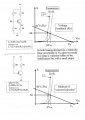
I have spent over an hour trying to find this answer. For example, Vcc is 7V, how do I calculate the ohm value of my base resistor to achieve a .7 base voltage? Or any other desired voltage.
Sorry for the typo but in the title, you can’t edit the title when editing a message.
Sorry for the typo but in the title, you can’t edit the title when editing a message.