ahh! how could i not tot of that.. hahah.. i tried to cover the photodiode and it worked.. the voltage went down to about 3V and increases as i open it up a bit..
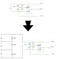
Hope everyone is doing fine After playing around with the previous circuit that i've got, i decided to use the same power source for another 3 10V output. So I'm thinking of doing this (as attached).. does it work like this? i just need a confirmation before i start soldering everything heheh..
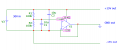
You have a small error in your diagram. You should never connect capacitor like you did in your diagram. Because now C1 and C2 form AC voltage divider for a supply voltage source. So any ripple present at supply rail are almost not attenuated (6dB). The correct diagram should look like this. And now all the ripples are bypass to ground.
I don´t think any ripple should be attenuated, the purpose is to keep the gnd rail in the middle of the supply, so without the cap the gnd will be in some slow stable relation to bottom rail, but it will rarely stay in the middle of the supply.
I don´t think any ripple should be attenuated, the purpose is to keep the gnd rail in the middle of the supply, so without the cap the gnd will be in some slow stable relation to bottom rail, but it will rarely stay in the middle of the supply.

 Facebook
 Google
 GitHub
 Linkedin