How do I connect my reader module?

Thread Starter

Dadu@

Joined Feb 4, 2022
155
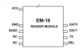
I want to interface EM-18 reader module with Arduino Uno. I don't know how to interface 4 pins connector on board to Arduino
I know third pin is TX pins I don't know which is VCC and ground

Kindly find the attachment

Mod: lightened your images.

EG 1308.png
 
Last edited by a moderator:

ericgibbs

Joined Jan 29, 2010
18,767
hi,
I don't understand why you are having a problem tracing those 4 Pins on the Base of the Module.

Both sets of pins are offset towards one end of the module , there are 4 pins on one side and 5 pins on the other side, it is a polarised base pin out.


EG 1312.pngEG 1309.png
 

MisterBill2

Joined Jan 23, 2018
18,179
Given that the TS does not understand the labels on that "reader" module, and that the TS does not present any labels for the pins on the micro board, it is up to somebody who has personally connected tis reader module to that micro module, and had it work, to provide the information. The others are guessing.
 

ericgibbs

Joined Jan 29, 2010
18,767
The others are guessing.
Hi Bill.
I am not guessing, the documentation for the devices is available on the web.
If you take the trouble of checking the PCB photo's and the documentation, they match.

Once again, you are placing doubts in the TS mind about the accuracy of the help provided by other posters.

Why do you do that, when you have obviously not taken the trouble to read through the available documentation ???

E
 

MisterBill2

Joined Jan 23, 2018
18,179
When "the information is so easily available on the web", which sometimes it is, other times not so easily available, why didn't the TS seek it and find the answer? Stating a question more completely is better because then it is clearer just what the TS is actually in need of.
AND, consider in post #1, the TS is seeking to know which pins on that 4 pin header are for Vcc and gnd, which those connections are not present on that header. But it is obvious from the photo that the PCB has a separate connector for an external supply of some voltage with some polarity. So a simple cable to that 4 pin header iis only part of what it will require, because power does not connect at that point.
Thus my suggestion that one who has actually made it work should reply.
 

ericgibbs

Joined Jan 29, 2010
18,767
He has posted a photo of the PCB base, the 4 contacts are ringed RED.

They perfectly match the documentation, I have posted a marked up of the 4 pins.

I have no idea what you are rambling about trying to create confusion on this Thread.


EG 1318.pngEG 1309.pngEG 1312.png
 

MisterBill2

Joined Jan 23, 2018
18,179
The TS makes a comment in post #1, relating to that same 4 pin header: " I know third pin is TX pins I don't know which is VCC and ground ". THAT is the basis for my comment. The TS certainly appears to be looking for a power connection on that 4 pin header.
No way am I trying to create confusion. That was never my intention, nor has it been in any of my posts. And when I make a guess, I state that it is a guess, which might be correct, or possibly not.
 
Top