How do I check in LTspice if I have met the specification in the question?

Thread Starter

Kai Chiang

Joined Oct 27, 2015
12
With reference to this diagram
Single-stage CS amplifier with CSL
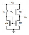
upload_2016-9-2_21-56-16.png
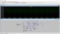
In LTspice I believe it looks like this
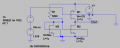
upload_2016-9-2_21-57-54.png

I am not so sure how do I check if my circuit met the specification in LTSPICE
1) Open-loop gain: > 50
2) Output voltage swing: > 1.2 Vp-p
3) Supply current: < 500 μA
4) DC Output voltage is 1.5V

What should I key into LTSPICE to check?
 

MrAl

Joined Jun 17, 2014
13,859
Hello,

You move your cursor to the Vout terminal and click. That gives you the waveform after you do a simulation run. That will tell you the DC voltage and AC voltage so you can calculate the gain too.
 

Thread Starter

Kai Chiang

Joined Oct 27, 2015
12
Hi
When I click run , I am not really which analysis I should use.
There is transient , AC analysis , DC sweep , Noise , DC transfer and DC op pnt.
If I want to find out the Vout of the voltage swing in LTspice, how should I go about? I know that the voltage can swing up 2.1Voltage and down to 0.9voltage since output voltage is given as 1.5V.
also which function should I use to check the gain of the circuit?
 

MrAl

Joined Jun 17, 2014
13,859
Hi,

Try both transient and AC and see if you can get some results.
For example, in AC you may be able to tell right away with the gain is.
In transient, you can look at the peaks and figure out the amplitude, then divide by the input voltage peak to peak for example.
 

crutschow

Joined Mar 14, 2008
38,916
Transient analysis is a time-domain analysis which calculates the actual voltages at all nodes using the models for the devices (most of which are generally non-linear).
It can only calculate results for one input frequency or waveform at a time.

The AC analysis is a frequency domain analysis which calculates the DC operating point and then linearizes the device gain based upon that bias point.
It can only have a sinewave (AC) as its source.
It then generates a frequency and phase response for the selected output node over the selected frequency range, using these linearized models.
Since this is a frequency domain analysis with linearized devices it makes no difference what the source AC voltage is as far as the relative gains are concerned.
But 1V is typically used for the AC source since then that corresponds to 0dB in the LTSpice calculations.
The output response in dB thus directly corresponds to the gain in dB from the input to the output.
 

KaiL

Joined Aug 30, 2014
69
Hi Thanks for your reply.
I would like to check if my circuit is correct in LTSPICE with reference to this
 

KaiL

Joined Aug 30, 2014
69
upload_2016-9-4_0-0-46.png

Not sure why it is only in 0.6V range ?_?
By right it should be the voltage should go up 2.1Voltage and down to 0.9voltage since output voltage is given as 1.5V. Did I do something wrong?
 
Last edited:

KaiL

Joined Aug 30, 2014
69
I see. The fourth leg is about Body source which i ground it as shown in my circuit diagram in LTspice. Thus, no body effect.
 

KaiL

Joined Aug 30, 2014
69
Why? Actually , I am not so clear about this ?_? I only know that if you connect it to ground , there will not be any body effect. I maybe wrong though since I have just started on MOSFET lesson.
 
Top