How can I revive this Acer laptop battery?

KeithWalker

Joined Jul 10, 2017
3,614
Wow, with a 331 ohm resistor in parallel, I get exactly 0V between every single pin. It's solid 0.00V between red-orange and orange-black. Every thing gets 0.00V. Whenever I remove the resistor in parallel, I get the values in the first post.
That suggests that the battery is past recovery but you cant lose anything by trying.
 

Thread Starter

rambomhtri

Joined Nov 9, 2015
606
Okay, I'm gonna do it today, may be in a few hours, and post back the results. Should I try red or orange as positive?
Everything inside me tells me it's the red wires, it has 2 of them, just like ground, it is right above the + sign, it's in the opposite side as ground... I think, since the battery is kind of messed right now, that the orange is higher due to this bad state, but as soon as there's charge, it will be red. Batteries normally have positive and negative in the opposite sides, and between them a clock, a thermistor, a data and a switch, 4 cables just like mine.
Should I try this in a well ventilated area in case there's smoke or fire?
Could it explode? Should I stay away from it while ot charges or you would charge it in front of your face, right in your desk?
Green light to create the 39 ohm resistor with 8 parallel little 331 ohm resistors?
 

KeithWalker

Joined Jul 10, 2017
3,614
Okay, I'm gonna do it today, may be in a few hours, and post back the results. Should I try red or orange as positive?
Everything inside me tells me it's the red wires, it has 2 of them, just like ground, it is right above the + sign, it's in the opposite side as ground... I think, since the battery is kind of messed right now, that the orange is higher due to this bad state, but as soon as there's charge, it will be red. Batteries normally have positive and negative in the opposite sides, and between them a clock, a thermistor, a data and a switch, 4 cables just like mine.
Should I try this in a well ventilated area in case there's smoke or fire?
Could it explode? Should I stay away from it while ot charges or you would charge it in front of your face, right in your desk?
Green light to create the 39 ohm resistor with 8 parallel little 331 ohm resistors?
Go ahead and try it. with the resistors in parallel. Keep your meter connected. Try the red and black. If the voltage does not does not increase after a few minutes the try orange and black. You will only be supplying about 100 mA of current so it will not charge up very quickly. If it starts getting hot or swells up, disconnect it. If you can get the voltage up to 6 volts, which will take several hours, it should take a charge when in the computer.
It's probably dead but you may get lucky.
 

Thread Starter

rambomhtri

Joined Nov 9, 2015
606
Go ahead and try it. with the resistors in parallel. Keep your meter connected. Try the red and black. If the voltage does not does not increase after a few minutes the try orange and black. You will only be supplying about 100 mA of current so it will not charge up very quickly. If it starts getting hot or swells up, disconnect it. If you can get the voltage up to 6 volts, which will take several hours, it should take a charge when in the computer.
It's probably dead but you may get lucky.
Thank you
 

Thread Starter

rambomhtri

Joined Nov 9, 2015
606
Oh, last quick question...
If when the battery is charged, the positive is +7.7V, that means that electrons will flow from positive to ground, right?

When the battery is almost dead and you want to charge it... shouldn't you apply an opposite voltage to move the charges from ground to positive?
Force electrons to go back to the positive?
In other words, connect the positive of the charger to the ground of the battery, and the ground of the charger to the positive of the battery?
I don't know much about this kind of stuff, but that's what I believe without having a clue.
 

KeithWalker

Joined Jul 10, 2017
3,614
Oh, last quick question...
If when the battery is charged, the positive is +7.7V, that means that electrons will flow from positive to ground, right?

When the battery is almost dead and you want to charge it... shouldn't you apply an opposite voltage to move the charges from ground to positive?
Force electrons to go back to the positive?
In other words, connect the positive of the charger to the ground of the battery, and the ground of the charger to the positive of the battery?
I don't know much about this kind of stuff, but that's what I believe without having a clue.
Positive of the charger to positive of the battery. The other way round, you will discharge the battery quite quickly!
 

Thread Starter

rambomhtri

Joined Nov 9, 2015
606
Positive of the charger to positive of the battery. The other way round, you will discharge the battery quite quickly!
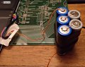
Ok, I've built the charging circuit, which is x8 resistors 331 ohm in series, that give us 41.5 ohm, and x5 AA batteries that gives us 8.2V.

To check if it's working or not, I've put the multimeter in ampmeter mode, short circuit, and connected the battery. I get exactly 0.00, mA no matter if I put the red-black or orange-black. How is it possible?
1.jpg 2.jpg
Yeah, a little bit rudimentary but it works, at least the resistors give me a rock solid value, and I've put a wire all across the resistors to make sure they are all solidly connected. As I said, 8.2V and 41.5ohm.

Just for fun I've used the DMM as an ampmeter and simply connected the resistors to the battery. I get 185mA of current, which is perfect, so my circuit is working fine.
 
Last edited:

KeithWalker

Joined Jul 10, 2017
3,614
Ok, I've built the charging circuit, which is x8 resistors 331 ohm in series, that give us 41.5 ohm, and x5 AA batteries that gives us 8.2V.

To check if it's working or not, I've put the multimeter in ampmeter mode, short circuit, and connected the battery. I get exactly 0.00, mA no matter if I put the red-black or orange-black. How is it possible?
View attachment 187428 View attachment 187429
Yeah, a little bit rudimentary but it works, at least the resistors give me a rock solid value, and I've put a wire all across the resistors to make sure they are all solidly connected. As I said, 8.2V and 41.5ohm.

Just for fun I've used the DMM as an ampmeter and simply connected the resistors to the battery. I get 185mA of current, which is perfect, so my circuit is working fine.
I hope you didn't connect the meter directly across the red/black wires in ammeter mode! That's asking for trouble!
The only way you can tell if the circuit is working is if you measure the voltage across the battery terminals when the charger is connected to see if the battery voltage increases gradually.
 

Thread Starter

rambomhtri

Joined Nov 9, 2015
606
No, no, no, hahaha, that would mean I shorted the battery. No I didn't.
Let me explain:
1. Did what's in your first drawing. Voltage gives 8.2V between black-red or black- orange. Just as if it wasn't plugged it in the battery.
2. Set the DMM to ampmeter. Put it in series, of course, to check the amps in one cable. Got 0.00mA.
3. Same as 2, but I simply skipped the battery, to check if the circuit I made worked. It works and the ampmeter read 185mA. Perfect.

So, looks like there's infinite ohm between red and black, because I get 8.2V between the cables of my whole circuit with the battery connected and without it.
 
Last edited:

KeithWalker

Joined Jul 10, 2017
3,614
No, no, no, hahaha, that would mean I shorted the battery. No I didn't.
Let me explain:
1. Did what's in your first drawing. Voltage gives 8.2V between black-red or black- orange. Just as if it wasn't plugged it in the battery.
2. Set the DMM to ampmeter. Put it in series, of course, to check the amps in one cable. Got 0.00mA.
3. Same as 2, but I simply skipped the battery, to check if the circuit I made worked. It works and the ampmeter read 185mA. Perfect.

So, looks like there's infinite ohm between red and black, because I get 8.2V between the cables of my whole circuit with the battery connected and without it.
That indicates that the battery was discharged to below the recovery point. It is now a paper-weight. Considering the cost of a new one, it was worth a try and you learned something new.
Regards, Keith.
 

Thread Starter

rambomhtri

Joined Nov 9, 2015
606
What a bummer, specially considering that a new battery is about $50... could it simply be a loose wire either in ground or positive?
As I told you, the laptop is just 45W, there's almost no heat, it's really, really weird that this battery suffered any damage due to use. it's only 2 years old. Is there something else I could try?
Disassemble it and check the cables?

I peeled one paper but it seems complicated to get to see the bare wires, it's all wrapped and wrapped.

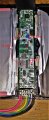
I'm a fighter and can't let it go, hahaha. I've finally disassembled the whole pack and here it is the circuit. Interesting, the cells actually do have charge, and I believe they are 100% charged?!
What is broken then?
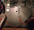
1.jpg

I do have a small camera for close ups, but nothing seems to be blown or broken. So, here's the fun part:
From 1 to red (positive) = +4.79V
From 1 to orange (???) = +2.51V
From 1 to yellow = +8.65V
From 1 to green = +8.24V
From 1 to blue = +8.24V
From 1 to black (ground) = +8.65V

Again, black magic, if from 1 to red is +4.79V, and from 1 to black is +8.65, from red to to black there should be -4.79V+8.65V = 3.86V, yet I get 0V!?!?!?!?!
 
Last edited:

Thread Starter

rambomhtri

Joined Nov 9, 2015
606
A resistor marked '331' is 330Ω - 33 * 10^1
Nice, didn't know that!

But hey, it works just fine, I made the circuit, although it doesn't matter because now we know it's not a matter of dead battery, the cells seem to be alright, fully charged 4.32V. Now the problem is in the IC, because somehow I can't get those 8.65V in the black-red terminals. Hope you can give me a hand about what can I do or test.
 

KeithWalker

Joined Jul 10, 2017
3,614
Nice, didn't know that!

But hey, it works just fine, I made the circuit, although it doesn't matter because now we know it's not a matter of dead battery, the cells seem to be alright, fully charged 4.32V. Now the problem is in the IC, because somehow I can't get those 8.65V in the black-red terminals. Hope you can give me a hand about what can I do or test.
I would not even try. The circuit is quite complex and contains a volatile I.D. which will be lost if you disconnect the cells. Then the computer would not accept it. You would have to work on it live. If the manufacturers didn't do this, they couldn't get away with charging such high prices for new batteries.
https://www.mpoweruk.com/bms.htm#smartbats
 
Last edited:

Thread Starter

rambomhtri

Joined Nov 9, 2015
606
Really?
I thought that now that we see the IC, it would be way easier to determine the problem. To measure here and there to diagnose. We can't give up now...
 

KeithWalker

Joined Jul 10, 2017
3,614
Really?
I thought that now that we see the IC, it would be way easier to determine the problem. To measure here and there to diagnose. We can't give up now...
If it was mine, I would consider that my only option would be to dis-assemble the battery and use the cells for other projects. I can't help you any more on this one.
 

Thread Starter

rambomhtri

Joined Nov 9, 2015
606
If it was mine, I would consider that my only option would be to dis-assemble the battery and use the cells for other projects. I can't help you any more on this one.
OK, thank you so much anyway. I hope an expert about these knows where is the problem. It looks like there's simply an open circuit somewhere, although the measurements don't match.

No one has ever replied to me about what I was asking:
If from 1 to red positive there's is +4.79V, and from 1 to black ground there is +8.65V, from red to to black there should be -4.79V+8.65V = 3.86V, yet I get 0V!?!?!?!?!
This is a violation of the second law of our beloved Kirchhoff!
 
Top