How can I recreate this type of switching?

Thread Starter

Popbang

Joined May 18, 2022
8
Hi guys,
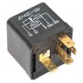
I want to recreate this relays action in a solid state form (JD142C-12v). It’s usually used to switch between high and low beam circuits on a car using a single momentary push button.
I’d like to make a small solid state version to use on a motorcycle. What would be the simplest way to go about it, components etc?
 

Attachments

Reloadron

Joined Jan 15, 2015
7,517
It could likely be done using a flip flop circuit in a D flip flop configuration and a pair of MOSFETs. Problem is I doubt you would come up with a better smaller package (footprint) than using the existing latching relay. Can a solid state version be made? Yes it can. Would it be practical? Not that I can see.

A Google of D Flip Flop circuits would be a start then have the Q and /Q outputs drive a few MOSFETs.

Ron
 

Reloadron

Joined Jan 15, 2015
7,517
Do you apply power or ground to turn on the headlights?
That determines whether you use an N-MOSFET or P-MOSFET to control the voltage.
Good point. I can't remember having a bike where lamp ground was switched. My current ride, a 92 Harley Electra Glide switches the high side so a P channel MOSFET would be the choice. That said all motorcycles are not created equal so be it high side or low side switching needs to be known. Can't recall ever having a bike with ground (low side) switching.

Ron
 

Thread Starter

Popbang

Joined May 18, 2022
8
Good point. I can't remember having a bike where lamp ground was switched. My current ride, a 92 Harley Electra Glide switches the high side so a P channel MOSFET would be the choice. That said all motorcycles are not created equal so be it high side or low side switching needs to be known. Can't recall ever having a bike with ground (low side) switching.

Ron
I use mini push buttons in most of my custom bikes. They switch to earth, so the trigger is earth, same as this relay. A positive output would be ideal.
 

Reloadron

Joined Jan 15, 2015
7,517
I use mini push buttons in most of my custom bikes. They switch to earth, so the trigger is earth, same as this relay. A positive output would be ideal.
Well alrighty then. You want what we call low side switching. That is we are switching the ground for high beam or low beam. Using a single button you would push once for high and push again for low beam. The way I would do it is using what is called a D Flip Flop circuit and two N channel MOSFETs. The CD4013 is an old D flip flop chip. You clock it which for what you want the push button comes in. The chip has two outputs which toggle back and forth on button push. Each output would drive an N channel MOSFET which would switch between Hi and Low beam grounds. The push button switch would need what is called switch debounce for a clean clock signal to the CD4013. Push button switches are not a nice clean make and break so in electronics you add debounce. Normally just a resistor / capacitor.

The problem with all of this is that when said and done you end up with a small circuit which will have a larger footprint than the simple mechanical relay we started with. The parts will need to be mounted on a PCB (Printed Circuit Board) and terminals added for connection points. You need to decide if all of this is practical?

Ron
 

Thread Starter

Popbang

Joined May 18, 2022
8
Well alrighty then. You want what we call low side switching. That is we are switching the ground for high beam or low beam. Using a single button you would push once for high and push again for low beam. The way I would do it is using what is called a D Flip Flop circuit and two N channel MOSFETs. The CD4013 is an old D flip flop chip. You clock it which for what you want the push button comes in. The chip has two outputs which toggle back and forth on button push. Each output would drive an N channel MOSFET which would switch between Hi and Low beam grounds. The push button switch would need what is called switch debounce for a clean clock signal to the CD4013. Push button switches are not a nice clean make and break so in electronics you add debounce. Normally just a resistor / capacitor.

The problem with all of this is that when said and done you end up with a small circuit which will have a larger footprint than the simple mechanical relay we started with. The parts will need to be mounted on a PCB (Printed Circuit Board) and terminals added for connection points. You need to decide if all of this is practical?

Ron
Thanks! That’s very helpful, a great starting point.
I’m sure I can fit it into a small enough package for my application. There is no need for terminals. It just needs a small length of wiring coming out.
I’ve seen products that do this same thing in a 25mm diameter by 10mm deep package. But they’re becoming harder to find and not readily available. Plus.. they’re very expensive..
 
Last edited:

Thread Starter

Popbang

Joined May 18, 2022
8
What are You wanting to install this on ?,
if it's a Custom-Bike, there are some great Modules available that will do anything You need ..........

Here's the entire Bike for ~$400.oo .........
https://viciouscycleworks.us/Item/JOKERSWSLEV

Here's some very basic Controls .........
https://namzcustomcycleproducts.com/product/nsc-01-momentary-to-latching-switch-module/
.
.
.
hi, yeah I know about most of the modules available, I’m actually a dealer for motogadget, highsider, Kellerman, axle joost etc.. I have been using their products on the bikes I build for some time. But all I want is a high/low beam circuit to use with a single push button. I was using the Highsider Wannadimmer module, which was perfect, but they’ve stopped making it. I’ve used other brands which have failed on me. So I want to create my own.
 

Thread Starter

Popbang

Joined May 18, 2022
8
Well alrighty then. You want what we call low side switching. That is we are switching the ground for high beam or low beam. Using a single button you would push once for high and push again for low beam. The way I would do it is using what is called a D Flip Flop circuit and two N channel MOSFETs. The CD4013 is an old D flip flop chip. You clock it which for what you want the push button comes in. The chip has two outputs which toggle back and forth on button push. Each output would drive an N channel MOSFET which would switch between Hi and Low beam grounds. The push button switch would need what is called switch debounce for a clean clock signal to the CD4013. Push button switches are not a nice clean make and break so in electronics you add debounce. Normally just a resistor / capacitor.

The problem with all of this is that when said and done you end up with a small circuit which will have a larger footprint than the simple mechanical relay we started with. The parts will need to be mounted on a PCB (Printed Circuit Board) and terminals added for connection points. You need to decide if all of this is practical?

Ron
I just re read what you said, maybe I wasn’t clear.
I need it to be switched with a negative, as one side of the push button will be earthed to the bike. But the headlights themselves need to be switched on the positive side as their negative side is earthed to the bike.
Is this still possible with the CD4013? do I need to swap to P channel mosfets?
 

LowQCab

Joined Nov 6, 2012
4,072
Do You have one Push-Button for Low-Beam, and a second Push-Button for High-Beam ?

Or is this a Single-Toggling-Push-Button where it's operation is Push-High , Push-Low ?

If You want to get fancy, You can have a Single-Push-Button that
Toggles between Off, Low, High, Off, Low, High, (repeat).

Making it really compact and Water-Proof is the tricky part.
.
.
.
 

Thread Starter

Popbang

Joined May 18, 2022
8
Y
Do You have one Push-Button for Low-Beam, and a second Push-Button for High-Beam ?

Or is this a Single-Toggling-Push-Button where it's operation is Push-High , Push-Low ?

If You want to get fancy, You can have a Single-Push-Button that
Toggles between Off, Low, High, Off, Low, High, (repeat).

Making it really compact and Water-Proof is the tricky part.
.
.
.
Yeah, just one single toggling push button that alternates between high and low beam everytime it’s pressed. I will probably end up casting it in resin in a small mold. I’ll try get it as compact as possible on a custom pcb.
 

Reloadron

Joined Jan 15, 2015
7,517
I need it to be switched with a negative, as one side of the push button will be earthed to the bike. But the headlights themselves need to be switched on the positive side as their negative side is earthed to the bike.
OK, now I got it finally. I would still do it as mentioned but on the headlight side use P channel MOSFETs and use the mentioned CD4013 for toggling between High and Low beam.

Ron
 

Reloadron

Joined Jan 15, 2015
7,517
There you go. Thank you LowQCab. You can see where the footprint will not be as small as the relay but the design will take in a wide range of headlamps from LED to filament. Least I forget, the CD4013 D flip flop has two flip flops per chip. You will have one unused flip flop. I suggest you tie the unused inputs to ground.

Ron
 

LowQCab

Joined Nov 6, 2012
4,072
Believe it or not,
the whole thing will fit on a 1-inch-square Printed-Circuit-Board.
The connecting Wires take up more Real-Estate than all the components combined.
Heat is my biggest worry, but even with the whole thing potted, it should still be OK.
.
.
.
 

eetech00

Joined Jun 8, 2013
3,951
Believe it or not,
the whole thing will fit on a 1-inch-square Printed-Circuit-Board.
The connecting Wires take up more Real-Estate than all the components combined.
Heat is my biggest worry, but even with the whole thing potted, it should still be OK.
.
.
.
Why not replace the opamp with the unused CD4013 and a differentiator?

Here's an alternate circuit. I replaced the opamp with the unused CD4013 (the CD4013 has two FF in a package)
so reduces the chip count to 1. I've also added a POR circuit so the U1B always initializes to a known state at power up.

1653091968974.png
 
Last edited:
Top