how can I obtain a clean PWM signal after having added dead time to my circuit?

Thread Starter

rfengineer28

Joined Apr 28, 2021
79
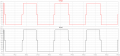
I am currently simulating this circuit below, however, i am running into a problem whenever the signal goes through the gate driver it comes out somewhat deformed. I already tried adjusting the bootstrap capacitor but that didnt help. only thing i can think of is maybe the dead time value being inadequate.

1654808118840.png


1654808151581.png
 

Attachments

Thread Starter

rfengineer28

Joined Apr 28, 2021
79
Looks like too much dead time.
How much dead-time do you have?
The truth is i have been very confused on how to calculate dead time and i have been pretty much playing with the values of the rc circuit. I do have a question though, am i supposed to be pulsing 1-4 in my circuit while simulating or is it correct to be doing in it in pairs like 1 and 2 on while 3 and 4 are off (pulse set to 0)?
 

MisterBill2

Joined Jan 23, 2018
18,179
What I see is exactly what a signal with delay time should look like, A bit of random drift during the time when all of the drivers are off. Dead time is intended to prevent "shoot through", which it seems to be doing very well.
 

crutschow

Joined Mar 14, 2008
34,285
i have been very confused on how to calculate dead time
You determine the rise and fall times of the MOSFET drain signals, and generate sufficient dead time so that the top MOSFET is off before the bottom MOSFET turns on, and vice-versa.
More dead-time than that can give the notch in the waveform you see.
 

Alec_t

Joined Sep 17, 2013
14,280
For the CD4000_v.lib models to work as intended, they need a positive supply node labelled "Vdd".
What are the V8 and V10 parameters?
 
Top