Hot Swapping Headphone Jack - Temporary Shorts During Insertion - How To Remedy?

Thread Starter

Mahonroy

Joined Oct 21, 2014
417
Hey guys,
I have a 3-wire temperature sensor (DS18B20) wired up to a headphone jack. I have the corresponding receptacle on the PCB. If the device is powered off before insertion of the plug, everything is fine.
However, inserting the jack while the device is running causes the device to reset. This is because during the insertion of a headphone jack, there are temporary shorts that occur:
* Sleeve gets shorted to the ring
* Sleeve gets shorted to the tip
* Ring gets shorted to the tip
Once its fully inserted nothing is shorting with one another.

I am having difficulty with trying to come up with a solution to this. I have not been able to google a solution yet.

Using a headphone jack/receptacle that has built in switches is not an option because the user has the option of using an audio extension cable as well. So the plug could be inserted at the PCB, but they could plug/unplug it at the other end, causing the same temporary shorts I mentioned above.

I am trying to think of a solution that maybe involves some diodes but I am just not sure. Any help/advice is greatly appreciated, thanks!

Here is a schematic for reference:
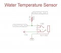
hot_swap_question1.jpg
In this schematic going from right to left, the rectangular box is the "sleeve", the middle connector is the "ring", and the last connector is the "tip" (in this case, this is the data line that is being pulled high to 3.3V).

And here is the datasheet to the audio jack/receptacle (I am using the "SJ1-3523N" version):
http://www.mouser.com/ds/2/670/sj1-352xn-series-535548.pdf
 

Thread Starter

Mahonroy

Joined Oct 21, 2014
417
I presume you're buying unterminated DS18B20 sensors?

Would putting the +5V at the tip solve your problem?
I am not sure what you mean by "unterminated DS18B20".

I don't believe that would solve the problem, because there is a point where the tip and the sleeve (in the receptacle) get shorted together momentarily. This would still cause the +5V to go into the GND.
 

Thread Starter

Mahonroy

Joined Oct 21, 2014
417
Would it be feasible to limit the current somehow on the red dots that I indicated?
How would I go about doing that? Either something that could restrict current, or would become an open if too much current, seems that would work wouldn't it?
hot_swap_question2.jpg

EDIT:
What if I add a TC1014 (datasheet below) at the two indicated red dots, would that do the trick? They are 50mA LDO Voltage Regulators with built in over current protection. I'm thinking if they are shorted to ground, then the LDO voltage regulators would simply just turn off momentarily? I'm not sure about the situation of the ring and the tip shorting though?
http://www.mouser.com/ds/2/268/21335b-29125.pdf
 
Last edited:

GopherT

Joined Nov 23, 2012
8,009
Power supplied through a headphone jack is asking for trouble. Get a proper 3-pin connector. Preferable a one-way connector that prevents the user from connecting with 180 degree flip that could reverse the polarity.
 

Thread Starter

Mahonroy

Joined Oct 21, 2014
417
Power supplied through a headphone jack is asking for trouble. Get a proper 3-pin connector. Preferable a one-way connector that prevents the user from connecting with 180 degree flip that could reverse the polarity.
Unfortunately this is not an option. Using an audio jack for a low powered devices like this is not unheard of. I am not using the audio jack as a power supply cable. Running a significant amount of power would be sketchy, but we are only talking a few milliamps here.
 

Thread Starter

Mahonroy

Joined Oct 21, 2014
417
Then what supplies power to the sensor?
Using an audio jack to power the entire circuit board would be using it as a power supply cable. (e.g. in place of a wall wart)

Like I said earlier...I am using this for data/signal transmission and we are talking a couple mA... this would not constitute as using it as a power supply cable.
 

ronv

Joined Nov 12, 2008
3,770
Using an audio jack to power the entire circuit board would be using it as a power supply cable. (e.g. in place of a wall wart)

Like I said earlier...I am using this for data/signal transmission and we are talking a couple mA... this would not constitute as using it as a power supply cable.
can't you run it on parasite power and not use the +5 volts?
 

Thread Starter

Mahonroy

Joined Oct 21, 2014
417
can't you run it on parasite power and not use the +5 volts?
I was not sure what the parasite power was so had to google it. Two things come to mind: if I do just use parasite power, that will consist of the data line and ground. The data line is still being pulled high to 3.3V, so when the plug is being inserted, it will still be shorted to ground momentarily.
I am using the +5V so I can get longer cable distance between the PCB and the sensor.
 

ronv

Joined Nov 12, 2008
3,770
I was not sure what the parasite power was so had to google it. Two things come to mind: if I do just use parasite power, that will consist of the data line and ground. The data line is still being pulled high to 3.3V, so when the plug is being inserted, it will still be shorted to ground momentarily.
I am using the +5V so I can get longer cable distance between the PCB and the sensor.
Oh, I thought it was shorting the +5 volts to ground that was the problem. :(
If you can't ignore the noise in code then I think your out of luck.
Edit:
Wait..... Isn't the data line the tip?
 

Thread Starter

Mahonroy

Joined Oct 21, 2014
417
Oh, I thought it was shorting the +5 volts to ground that was the problem. :(
If you can't ignore the noise in code then I think your out of luck.
Edit:
Wait..... Isn't the data line the tip?
Every pin gets shorted to every pin during insertion (every combination, see my original post where I describe this).
So yes, 5V shorting to ground is 1 of the problems, but not the only problem.

Its not a code issue... shorting any of the power rails to ground causes the device to reset, because this causes a current overload scenario with the voltage regulators (so the voltage regulators shut off until the high current is removed).

I do not believe I am out of luck, I refuse to believe that. What about my ideas I mentioned earlier? No one commented on those yet.
 

ronv

Joined Nov 12, 2008
3,770
Does it not look like this?

If it does I can't see any way for the tip to short to anything but the tip. Now that I think about it I can't see how the barrel shorts to the +5 either. Maybe a picture?
But to answer your question: Yes you could probably add a small resistor to the +5 volt line to limit the current.
 

Thread Starter

Mahonroy

Joined Oct 21, 2014
417
Does it not look like this?

If it does I can't see any way for the tip to short to anything but the tip. Now that I think about it I can't see how the barrel shorts to the +5 either. Maybe a picture?
But to answer your question: Yes you could probably add a small resistor to the +5 volt line to limit the current.
Its really similar. Mine is not clear so I cannot see inside of it. But I can connect a volt meter to every combination of pins and I can see that they momentarily conduct at some point during the insertion.

My main question was can I use a LDO Voltage regulator (50mA) at the 2 red markings I marked for a current limiter. The LDO I was looking at is the TC1014
 

ronv

Joined Nov 12, 2008
3,770
Its really similar. Mine is not clear so I cannot see inside of it. But I can connect a volt meter to every combination of pins and I can see that they momentarily conduct at some point during the insertion.

My main question was can I use a LDO Voltage regulator (50mA) at the 2 red markings I marked for a current limiter. The LDO I was looking at is the TC1014
Well, that's a bummer.
The current is already limited by the 4.7k in the data line.
I don't think you need a regulator for the +5 just send it out thru say 220 ohms. The sensor only draws 1.5 ma max.
I fear your problem may be that whatever is looking at the sensor data may just be looking for a change of state to start running. But maybe not.:D
 

Thread Starter

Mahonroy

Joined Oct 21, 2014
417
Well, that's a bummer.
The current is already limited by the 4.7k in the data line.
I don't think you need a regulator for the +5 just send it out thru say 220 ohms. The sensor only draws 1.5 ma max.
I fear your problem may be that whatever is looking at the sensor data may just be looking for a change of state to start running. But maybe not.:D
Thanks again for the reply. Your not understanding the problem correctly... take a look at the schematic I posted: the prong inside the receptacle/jack has 5V on it. When I insert a plug, this prong gets connected directly to the ground plug... this will draw a LOT more than 1.5 ma... this is a short circuit. The 5V rail is getting shorted to ground, it has nothing to do with the sensor. Pretend the temperature sensor does not even exist and its just a blank plug with nothing connected to it.
 

ronv

Joined Nov 12, 2008
3,770
Thanks again for the reply. Your not understanding the problem correctly... take a look at the schematic I posted: the prong inside the receptacle/jack has 5V on it. When I insert a plug, this prong gets connected directly to the ground plug... this will draw a LOT more than 1.5 ma... this is a short circuit. The 5V rail is getting shorted to ground, it has nothing to do with the sensor. Pretend the temperature sensor does not even exist and its just a blank plug with nothing connected to it.
Yes, I know. Put 220 ohms in series with the +5 volts before it gets to the jack. That way when the plug shorts it out it only draw 22 ma instead of a short.
 

Thread Starter

Mahonroy

Joined Oct 21, 2014
417
Yes, I know. Put 220 ohms in series with the +5 volts before it gets to the jack. That way when the plug shorts it out it only draw 22 ma instead of a short.
Ah I see what you mean.

Am I correct that the resistor will dissipate 0.113 watts under this condition? E.g. 0.022 amps * 5 volts = 0.113? So I could just use a 1/6 watt 0805 resistor and be good to go?
 
Top