Horizon Fitness Treadmill 4.2T Control board Inrush Current Limiter

Thread Starter

Limewater

Joined Jan 25, 2018
4
Hello!

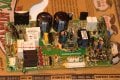
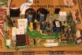
I have the MT0702119 Control board for a Horizon Fitness 4.2T treadmill I am hoping to fix. It has several obvious problems.

One of them is a hole straight through the single large inrush current limiting resistor next to the AC power leads. Unfortunately, this means I cannot read any part number or specifications off of it. I have seen a couple of threads about this line of motor controllers on here, and was hoping someone might be able to suggest some parameters.

Thank you very much!
 

Thread Starter

Limewater

Joined Jan 25, 2018
4
Is it a VDR/MOV or an actual resistor, can you post a pic of it.
Also is this a 120v or240v model?
Max.
Thank you very much!

I believe it is an MOV. I'll take a stab at attaching pictures. It is a 120V model.
In the first photo, the component in question is on the far left, with the obvious scorch marks around it.
In the second photo, you can see a 'C', but the rest of the text is gone from when it burned out.

Again, thank you very much!

DSC_0068.jpg DSC_0069.jpg
 

MaxHeadRoom

Joined Jul 18, 2013
28,684
If it is a MOV across the AC in, you should be able to remove it and test the board, it normally only comes into play when large spikes are seen on the power rail.
I could select one that should work if you can confirm by examination or meter reading it is across the AC in.
Max.
 

Thread Starter

Limewater

Joined Jan 25, 2018
4
If it is a MOV across the AC in, you should be able to remove it and test the board, it normally only comes into play when large spikes are seen on the power rail.
I could select one that should work if you can confirm by examination or meter reading it is across the AC in.
Max.
It is across the AC in. I really appreciate your help.
 

IamJatinah

Joined Oct 22, 2014
136
Hold up....that is not an MOV rather a NTC thermistor. That part is also not across the AC Line as would be an MOV. That part is a thermistor in what was called the "precharge circuit". If this part is ripped, you have more possible trouble further downstream, as in check the bridge rectifier, and that main FET which is an IRFP250. Also, if the switching FET is shorted, the kickback diode will be fried as well. The thermistor can be replaced with a 30A device, say the Mouser part 995-SL32-1R030 also found at Digikey.
This part is only in the circuit for 1.2-seconds and is then strapped out by the relay right next to the precharge relay, which then supplies raw, unrestricted current flow to the main bridge rectifier and motor drive circuits.
This board also has a design issue, and is replaced with Horizon part 032669 and/or 032671.
Good Luck ;o)
 

IamJatinah

Joined Oct 22, 2014
136
?????????????
Max.
Hi Max, ... in this design used by Johnson, they have 4 relays, a set of 2 for lift up/down, and a set for what was called precharging and motor rail pass.

The device I often saw blow is the NTC thermistor that is seldom marked and was a chinese part. Now this thermistor sits in series with the relay contacts of the Precharge relay which has the purpose of controlling In-Rush of those larger storage capacitors, of 1000uf 200v each x2 or x3 depending on year of manufacture and the motor drive rail. These capacitors cannot charge excessively fast as that in-rush could damage the main rectifier, internally prematurely cook the caps and worse, without a limiting element, we had seen relay contacts "weld" in place, contacts stuck and unable to clear, very ugly scene.

So, to avoid relay welding and ripped rectifiers that were rated at 35A constant and 50A spike that were also vaporizing at powerup if the pwm was present at the press of start and no limiting, they decided to add the precharge relay and thermistor which turns on first when a user presses Start, this completes the AC input to the main motor rail rectifier, which then allows storage charging and motor +V_Bulk for switching by the main FET, the IRFP250. * Critical step for micro * "IF" +V_Bulk doesn't reach 150vdc and/or the topside of the main FET sits anywhere near hot-ground (due to a short say), the onboard micro will turn OFF that precharge and disable the main motor relay as well. Protecting the board and user from a possible runaway.

IF the precharge relay gets energized and there is a shorted bridge rectifier or the main FET, that relay is too slow to open to save the thermistor and it gets blown apart with the vast AC inrush ;o)
IF the precharge circuit see's +V_Bulk and a high on the FET short-detect circuit, the micro enables the relay right next to it, called the "Safety Relay" or main motor rail relay, and supplies raw AC input to the bridge and motor drives. ;o)

Hope I didn't confuse ya....I should draw this out for you, it's so simple and removes a series thermistor on high current AC rails nicely, but the drawback here, was if we energized into a short, we already blew the NTC by the time we could dampen the precharge relay.... replacing that NTC and retrying would again rip the NTC.

This was changed in the next software spin for the PIC that was used. The board itself had a few issues and is upgraded thru the manufacturer or most servicers.
 

IamJatinah

Joined Oct 22, 2014
136
jhtprechg.jpg
Like this a bit, snubbers around both relay contacts, K1 first precharges thru NTC1 if all appears good, K2 energizes and K1 precharge relaxes ;o)
 

Rehan2601

Joined Dec 26, 2021
2
Hello everyone
I hope you all are doing well.
I just wanted to know what is this TZR in the attached image as this component is missing from my control board and I want to replace it.
The Incline function in my treadmill is not working, can this be the reason for it not functioning as intended??
Any help will be much appreciated.
Thanks In advance
May god bless you all.
 

Attachments

jatinah

Joined Jul 26, 2010
20
Hello everyone
I hope you all are doing well.
I just wanted to know what is this TZR in the attached image as this component is missing from my control board and I want to replace it.
The Incline function in my treadmill is not working, can this be the reason for it not functioning as intended??
Any help will be much appreciated.
Thanks In advance
May god bless you all.
Hi There, I think the Tzr part should look like the 3A Diode-like part(1.5ke200a for US versions, 1.5KE400A for Euro versions) behind the round disc that looks to be blown which is a different type of part all together. If the NTC (Round Disc) is blown open, there is usually a reason for that(possibly a shorted Tzr could do it), which lies further downstream from there. The NTC can be replaced with a 30A(.5-ohm) device but not before correcting the issue further down, or it too will rip apart. Good Luck.
 

Rehan2601

Joined Dec 26, 2021
2
Hi There, I think the Tzr part should look like the 3A Diode-like part(1.5ke200a for US versions, 1.5KE400A for Euro versions) behind the round disc that looks to be blown which is a different type of part all together. If the NTC (Round Disc) is blown open, there is usually a reason for that(possibly a shorted Tzr could do it), which lies further downstream from there. The NTC can be replaced with a 30A(.5-ohm) device but not before correcting the issue further down, or it too will rip apart. Good Luck.
Hello jatinah
Thank you so much for your response.
I am really sorry but in my previous comment, I attached the screenshot with the arrow pointing to the wrong component and I noticed it now.
I request to please check the attachment in this comment if possible.
Actually i wanted to know about the yellow round disc component.
Thanks a lot again.
May God Bless You
 

Attachments

Top