Hooking up my LCD

Thread Starter

beeson76

Joined Apr 19, 2010
211
Just wondering if anyone can help me with my LCD now. This is kinda a continuation of the thread Building My First Microcontroller Circuit by me (beeson76).

I believe everything is correct as far as connections. When I plugged it in I got nothing but black boxes on the first line. I did some reading and found out that Pin 3 controls the contrast, by controlling current I believe--maybe its voltages. So I stuck on a Potentiometer and can now control the contrast. Here is the website for datasheet. It is a simple little LCD (C-1602A-1YN from Jameco). For the circuit I have 7.5vdc 300 ma AC adaptor going through a 7805 Voltage Regulator. Voltage output is 5 volts which I have going to my Pin 2 of the LCD. I have ground coming from Pin 1 that goes to ground of my Voltage Regulator. What should be connected to Pin 3.

This is my first circuit with a microcontroller, and certainly my first circuit with LCD attached. Any help is greatly appreciated. Also maybe website with LCD schematics would be awesome too. I certainly appreciate any help. Thanks
 

BMorse

Joined Sep 26, 2009
2,675
I though you said you had the contrast working?? Which pin did you connect the pot to?? Pin 3 of an LCD is usually the contrast control input....

You need to connect the center pin (wiper) of the pot to that pin, and connect one side of the pot to VCC(+) and the other to GND.... make sure to check the datasheet for the proper ratings for the pot, I believe a standard is somewhere between 20K to 100K.


B. Morse
 
Your LCD module has 16 pins so it may use the standard HD44780 commands and pinout.
[URL=http://en.wikipedia.org/wiki/HD44780_Character_LCD]Wikipedia[/URL] said:
1. Ground
2. VCC (+5V)
3. Contrast adjustment
4. Register Select (R/S)
5. Read/Write (R/W)
6. Clock (Enable)
7. Bit 0 *
8. Bit 1 *
9. Bit 2 *
10. Bit 3 *
11. Bit 4
12. Bit 5
13. Bit 6
14. Bit 7
15. Backlight Anode (+)
16. Backlight Cathode (-)
* = only needed for 8-bit operation, if using 4-bit mode then leave these disconnected.
 

Thread Starter

beeson76

Joined Apr 19, 2010
211
Sorry BMorse. I do have the pot connected to Pin 3. I have the the middle pin connected to Pin 3 and one of the "outer pins" connected to Vcc. The other pin is not connected to anything because the place where I found the information didn't tell me to connect it to ground. I will do that. That could be why the circuit is acting a little "weird" like when I push the button to display on the lCD it kinda like shorts out and just goes blank. I will give that a try. I wish I could send a schematic of my circuit but I really don't know how to except on autocad I could draw something up.
 

BMorse

Joined Sep 26, 2009
2,675
Sounds as if you have more than just a contrast connection issue, that should have nothing to do with what you are sending to the LCD, is there anyway you can post the code you have for the LCD routines?? and how you have the LCD connected to the pic?

B. Morse
 

Thread Starter

beeson76

Joined Apr 19, 2010
211
Thanks BMorse for the reply. I do believe I am making a little progress. When I hooked up the ground on the Pot, I now have 2 lines of black boxes. I can adjust the contrast for both lines. Before, it was just one line of black boxes. Here is the main code

Rich (BB code):
/*This program controls a matrix switch.  The switch consists of 3 columns and 4 rows.
//Whenever a button is pushed, that button  is displayed on an LCD screen.
//
*/

#include <htc.h>
#include "lcd.h"

#define  KEY_PORT				PORTB											
#define  KEY_SET(bits)			KEY_PORT |= (bits)			
#define  KEY_CLR				KEY_PORT &=~ (bits)			
#define	 KEY_FLP(bits)			KEY_PORT ^= (bits)			
#define  KEY_IN(bits)			TRISB |= (bits)				
#define  KEY_OUT(bits)			TRISB &=~ (bits)			
#define  KEY_COL				0b10000011							 
#define  KEY_ROW				0b01111000					
#define  DelayS(T)				{unsigned char i; for (i = 0; i < T * 10; i++) __delay_ms(100);}
#define  _XTAL_FREQ				4000000						//Needs to be set for __delay_ms

__CONFIG (XT, WDTDIS, PWRTEN, BORDIS, LVPDIS, UNPROTECT);


unsigned char key_read(unsigned char in_bits, unsigned char out_bits)
	{
		KEY_IN(in_bits);
		KEY_SET(out_bits);
		KEY_OUT(out_bits);
		return KEY_PORT & in_bits;
	}

unsigned char key_detect(void)
	{
		unsigned char tmp1, tmp2;
		tmp2 = key_read(KEY_ROW, KEY_COL);
		tmp1 = key_read(KEY_COL, KEY_ROW);
		return tmp1 | tmp2;
	}

main ()											
{																				

//TRISA = 0x00;										//Set PORTA to outputs
TRISB = 0xFF;										//Set PORTB to inputs
TRISC = 0x00;										//Set PORTC to outputs
RBPU = 0;
//ANSEL = 0;
//ANSELH = 0;
//CM1CON0 = 0;
//CM2CON0 = 0;

//OPTION = 0b01010101;

lcd_init();

char key;

while (key_detect() == 1)  							//Loops When Key is Pressed
continue;
{

key = key_detect();									//Referring to key_detect() function.  Returns key pressed.

switch (key)
	{
		case 0b00100001:							//Column 1 Row 4--Switch 12
			RA0 = 1;
			lcd_goto(0x00);
			lcd_puts("Switch 1");
			DelayS(1);
			lcd_clear();
			break;
		case 0b01000001:							//Column 1 Row 3--Switch 11
			//RA1 = 1;
			lcd_goto(0x00);
			lcd_puts("Switch 2");
			DelayS(1);
			lcd_clear();
			break;
		case 0b00010001:							//Column 1 Row 2--Switch 10
			//RA2 = 1;
			lcd_goto(0x00);
			lcd_puts("Switch 3");
			DelayS(1);
			lcd_clear();
			break;
		case 0b00001001:							//Column 1 Row 1--Switch 9
			lcd_goto(0x00);
			lcd_puts("Switch 4");
			DelayS(1);
			lcd_clear();
			break;
		case 0b00100010:							//Column 2 Row 4--Switch 8
			lcd_goto(0x00);
			lcd_puts("Switch 5");
			DelayS(1);
			lcd_clear();
			break;
		case 0b01000010:							//Column 2 Row 3--Switch 7
			lcd_goto(0x00);
			lcd_puts("Switch 6");
			DelayS(1);
			lcd_clear();
			break;
		case 0b00010010:							//Column 2 Row 2--Switch 6
			lcd_goto(0x00);
			lcd_puts("Switch 7");
			DelayS(1);
			lcd_clear();
			break;
		case 0b00001010:							//Column 2 Row 1--Switch 5
			lcd_goto(0x00);
			lcd_puts("Switch 8");
			DelayS(1);
			lcd_clear();
			break;
		case 0b10100000:							//Column 3 Row 4--Switch 4
			lcd_goto(0x00);
			lcd_puts("Switch 9");
			DelayS(1);
			lcd_clear();
			break;
		case 0b11000000:							//Column 3 Row 3--Switch 3
			lcd_goto(0x00);
			lcd_puts("Switch 10");
			DelayS(1);
			lcd_clear();
			break;
		case 0b10010000:							//Column 3 Row 2--Switch 2
			lcd_goto(0x00);
			lcd_puts("Switch 11");
			DelayS(1);
			lcd_clear();
			break;
		case 0b10001000:							//Column 3 Row 1--Switch 1
			lcd_goto(0x00);
			lcd_puts("Switch 12");
			DelayS(1);
			lcd_clear();
			break;
	}


}
}
Here is my LCD code
Rich (BB code):
#include <htc.h>
#include "lcd.h"

void pause(unsigned short usvalue);

#define		LCD_RS		RC1
#define		LCD_RW		RC2										
#define		LCD_EN		RC0
#define		LCD_DATA	PORTC
#define		LCD_STROBE()	((LCD_EN = 1),(LCD_EN = 0))

void
lcd_write (unsigned char c)
{
										//(cccc) = clearing bit - this is what is LCD_STROBE()
										//(kkkk) = keeping bit - this is kept because of LCD_RS, LCD_RW, LCD_EN

	
						//(& 0bcccckkkk) clearing top nibble of LCD_DATA and keeping bottom nibble of LCD_DATA
					//(| 0bkkkkcccc) filling top nibble of LCD_DATA with top nibble of c
							//sending top nibble to LCD
    					//clearing top nibble of LCD_DATA and keeping bottom nibble of LCD_DATA
     		//moving bottom nibble of c to high bits of LCD_DATA
    						//sending top nibble of LCD_DATA to LCD

	pause(1);
    LCD_DATA = (LCD_DATA & 0x0F) + (c & 0xF0);								
	LCD_STROBE();
	LCD_DATA = (LCD_DATA & 0x0F) + ((c & 0x0F) << 4);							 	
	LCD_STROBE();


}

void
lcd_clear(void)
{
	LCD_RS = 0;
	lcd_write (0x1);
	pause(2);
}

void 
lcd_puts(const char *s)
{
	LCD_RS = 1;
	while (*s)
		lcd_write(*s++);
}

void
lcd_putch(char c)
{
	LCD_RS = 1;
	lcd_write(c);
}

void
lcd_goto(unsigned char pos)
{
	LCD_RS = 0;
	lcd_write (0x80 + pos);
}

void
lcd_init()
{
	TRISC = 0;
	LCD_EN = 0;													 
	LCD_RS = 0;
	LCD_RW = 0;

	pause(15);
	
	LCD_DATA &=0x0F;
	LCD_DATA = 0x30;
	LCD_STROBE();
	
	pause(5);
	LCD_STROBE();
	
	pause(1);
	LCD_STROBE();
	
	pause(5);
	LCD_DATA &= 0x0F;
	LCD_DATA = 0x20;
	LCD_STROBE();
	

	lcd_write (0x28);										
	lcd_write (0x0F);										
	lcd_clear();					
	lcd_write(0x06);											
}
 

BMorse

Joined Sep 26, 2009
2,675
Yes that is definitely a good sign, it is even a good sign that your code for initializing it is working, since usually before initializing it for a 2 line display, it will only show 1 row of "boxes"....

Try adding a line of code after initializing it to test it if is working properly :
Rich (BB code):
lcd_write("Hello World!");
 

Thread Starter

beeson76

Joined Apr 19, 2010
211
Should I have DB0 to DB3 tied to ground? I am using the LCD in 4 bit mode therefore I have nothing on DB0 to DB3.
 

Thread Starter

beeson76

Joined Apr 19, 2010
211
Well I guess I made a mistake. I am not getting 2 rows of black boxes. It is still at one row of black boxes. So does that mean that the LCD is not inializing.
 

BMorse

Joined Sep 26, 2009
2,675
yes, that is correct. Usually when the LCD is first powered up its controller defaults to a 1 line display, after you initialize it for a 2 line then it will recognize the 2nd line....

If I remember correctly from your other post, you were trying to swap the 4 bits the LCD was actually connected to, did you wire the LCD data bits D4 to D7 to those I/O pins you are using in the code?? Normally in a standard configuration, the LCD will use the upper nibble of the port, D4 to D7 will connect to that ports D4 to D7

and also I believe you are using the other 4 data bits to control the LCD's control pins, which I believe will be affected anytime data is written to the port. In my experience, I always use those other four IO lines as inputs, then they are not affected by writing to the port, and I just use another port to control the LCD's RS, R/W and E control lines.....

I believe if you try this, you will see what I am talking about:

Set the control line RS to high and write anything to the port, you will see after writing to the port that RS will now be low, since half of the ports data is masked with 0000, which will turn all outputs on those 4 I/O lines to go low........

B. Morse
 
Last edited:

BMorse

Joined Sep 26, 2009
2,675
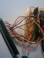
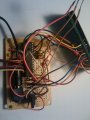
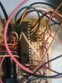
Ok, after looking at your pics, and if I remember correctly, you had swapped nibbles on the port and moved all the control lines from PortA to the lower nibble of PortC which is also the data for the LCD.....

The way you have it wired up, (except for the control lines) is exactly how the program should work without the modifications you did to swapping the upper and lower nibble, you need to revert back to the original LCD code and move your control lines to another port, and then just use those pins as inputs so they are not affected by the write to the port.

B. Morse
 

Thread Starter

beeson76

Joined Apr 19, 2010
211
To answer your first question. I am using d4-d7 on my upper nibble of my port (Port C Pins 4-7). If you can see from the picture I have D4-7 from my LCD (colors red, blue, yellow, and black) going to my Port C Pins 4-7. Again I am using the PIC16F886. I have simulated the code with Real Pic Simulator 1.1 and everything appears to be fine. I sure hope that isn't the problem. I guess I got in over my head trying to keep all the data and control lines on the same Port.

Back to the pictures all pink wires are normally ground and gray are 5 volt. My Pins 4(brown) ,5(purple) ,6(light brown) on my LCD are hooked to pins RC0-RC2 of my chip.
 

BMorse

Joined Sep 26, 2009
2,675
I tried to do the same with a PIC16F887 and a pic16F628A, and I ran into that write to port issue where it kept changing my control lines to low, so I moved the control lines to another port and it worked fine with Hi-Techs LCD demo code without modifications to the actual code....

B. Morse
 

Thread Starter

beeson76

Joined Apr 19, 2010
211
Thanks for the replies BMorse. I appreciate it. If I am understanding you correctly, if I would revert back to my old code and have PortA as my control lines and PortC as my data lines, I would need to make set PortA as inputs? Is that correct? PortC would be outputs wouldn't it?
 

BMorse

Joined Sep 26, 2009
2,675
Thanks for the replies BMorse. I appreciate it. If I am understanding you correctly, if I would revert back to my old code and have PortA as my control lines and PortC as my data lines, I would need to make set PortA as inputs? Is that correct? PortC would be outputs wouldn't it?

You only have to set the pins you are using on PORTA as outputs (the control lines (RS, R/W,E) are inputs to the LCD, so they should be outputs on the PIC), and only have to set the upper 4 bits of PORTC as outputs to write data to the LCD (the ones connected to D4 to D7 of the LCD), you can do what ever you want with the rest of the pins on those ports......


B. Morse
 

Thread Starter

beeson76

Joined Apr 19, 2010
211
I am going to try to use your suggestions. Do you think I should keep the modified LCD code and just change RS/RW/E to PORTA Pins 0,1,2. If I do that then I should not have to change anything except just rewiring from the Pins 0,1,2 of PORTC to PORTA. Is that correct?
 

BMorse

Joined Sep 26, 2009
2,675
I am going to try to use your suggestions. Do you think I should keep the modified LCD code and just change RS/RW/E to PORTA Pins 0,1,2. If I do that then I should not have to change anything except just rewiring from the Pins 0,1,2 of PORTC to PORTA. Is that correct?

That could work, but didn't you also swap the nibbles being sent to the LCD port? If you did, it still may not work....

B. Morse
 
Top