homemade power supply issue

Thread Starter

lokeycmos

Joined Apr 3, 2009
431
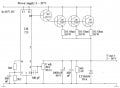
i have a homemade variable regulated power supply based on the lm723 ic. i have attached a schematic of it. i am having a couple issues that im hoping we can figure out. the first issue is that between 13 and 20 volts it makes a rapid "ticking" sound. i cant tell where it is comming from. the second issue is for example, when i put a load of just a couple amps it makes a high pitched "sqealing" sound. i cant tell where that is comming from either. other than that it works great.

the power supply can handle 5 amps, and is adustable from 2 volts to 32 volts. i have the dc in filtered by 36,000uF

any help or suggestions would be greatly appreciated
 

Attachments

I don't see anything that I recognize as a potential audible noise source. I believe it's usually coils that do that. Is it possible that the noise is coming from whatever is supplying 40V to your regulator? Maybe try putting a 40Ω resistor directly across the source and see if that causes the noise. (That's a fair bit of power, though. Use a 50W resistor and gloves or a switch or something, and don't leave it connected for too long. You're just trying to see if the noise is coming from somewhere else!)

As an aside, your regulator stage burns up a lot of power in the 2N3055 transistors. A buck regulator (for example, based on the cheap and easy-to-use MC33063) would be much more efficient, particularly at lower voltages (e.g. 2-20V, from your 40V input).
 

SgtWookie

Joined Jul 17, 2007
22,230
You realize that you're operating the IC at the absolute maximum voltage rating, right?

This generally is not a good idea. If your unregulated supply wanders over 40v, you may see smoke very quickly.
 

bountyhunter

Joined Sep 7, 2009
2,512
between 13 and 20 volts it makes a rapid "ticking" sound. i cant tell where it is comming from. the second issue is for example, when i put a load of just a couple amps it makes a high pitched "sqealing" sound.
control loop is oscillating. I'd wager the R-C components at the bottom left of the scematic are the compensation parts.
 

ifixit

Joined Nov 20, 2008
652
Some changes I would make...
  1. The 100pf should connect between the inverting input and the compensation pin (9). You have it on pin 13.
  2. Add a 1K resistor between the base of the BD243C transistor and the output to improve turn off time.
  3. Add a 100 resistor between the bases of the 2N3055 transistors and the output to improve turn off time.
  4. Change the 1000uF to 100uF. The output is regulated so excessive filtering is not needed.
  5. The 100nF should not be needed and can likely be removed.
Good Luck
 

Thread Starter

lokeycmos

Joined Apr 3, 2009
431
thank you ifixit for your helpful reply,

  1. Add a 1K resistor between the base of the BD243C transistor and the output to improve turn off time.
  2. Add a 100 resistor between the bases of the 2N3055 transistors and the output to improve turn off time.
do you mean from the bases to the emitters or from the bases directly to the final output? what exactly is this going todo? can you please elaborate on "turn off time"

if you look at the datasheet for the lm723 @ http://cache.national.com/ds/LM/LM723.pdf

pin 13 is the compensation pin. pin 9 is Vz, im not sure what vz is. am i missing something?
 

ifixit

Joined Nov 20, 2008
652
The Fairchild uA723 perliminary data sheet (from July 1968) I have is numbered incorrectly with regards to the DIP package. Sorry about that.. I hope I didn't just 'date' myself :). Pin 13 is the correct pin to use.

The base resistors I suggested ensure the B-E capacitance is discharged quickly when the 723 is not sourcing base current to the BD243C. The regulator control loop needs to work as good at lowering the output voltage as it does to raise the output voltage. This gives a good transient response times when heavy loads are attached or removed from the output.

The resistor will likely work just as well connected between base and emitter of the BD243C or 2N3055s. Just use one 100 res from the bases of the 3 2N3055s.

Done of the above may actually fix your problem however.

Do you have a scope you can use to look for the unwanted oscillations that may, or may not exist?

Regards,
ifixit
 

Thread Starter

lokeycmos

Joined Apr 3, 2009
431
thats an excellent idea! we have scopes in the electronics lab at the college. were just getting into scopes, anything inparticular i should look for on the readout other than the standard ripple voltage?
 

Thread Starter

lokeycmos

Joined Apr 3, 2009
431
thank you guys for all your advice. i figured it out. i replaced the 100pf compensation capacitor with a 470pf and it took care of all the ticking and squealing.
 

MaxSmoke

Joined Oct 29, 2009
35
I was thinking the same thing too Bill, fold-back current limiting would be a good feature and once you have fold-back current limiting, you can consider adding crow-bar over voltage protection.

LokeyCMOS do you have an input fuse on this PSU?
 
Top