 Facebook
 Google
 GitHub
 Linkedin
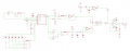
Frequency Counter
The square wave is fed into a digital input on an ATMega328 microcontroller. The digital input is triggered every time the square wave rises above the logic high threshold. The microcontroller samples the pin at a high rate and counts the number of cycles per second. This number is sent to the display via the MAX7221 display driver.
https://forum.allaboutcircuits.com/attachments/frequency-counter-png.74142/
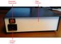
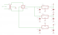
Power Supply
The step down isolation transformer is fed through a bridge rectifier. The center tap is tied to ground to provide both a positive and negative supply. The rectified voltage is regulated to a ±12 V line and a +5V line (for the digital logic ICs).
https://forum.allaboutcircuits.com/attachments/power-supply-png.74141/
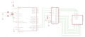
XR2206 and Amplifier
The XR2206 is configured according to the recommended circuit on the datasheet. The output is selected via a 3x3 rotary switch. This toggles the output feed, the symmetry adjustment, and the amplitude fine adjust, allowing these variables to be configured independently for each waveform. The XR2206 output is fed through a buffer amplifier and then a potentiometer to control amplitude. After this, the wave is summed with a DC voltage to adjust the DC offset. The AD811 amplifier drives the final output stage.
https://forum.allaboutcircuits.com/attachments/xr2206-png.74140/
Attachments
-
 41.5 KB Views: 708
 -
 1.9 MB Views: 714
 -
 1.7 MB Views: 764
 -
 25.4 KB Views: 296
 -
 17.2 KB Views: 192
 -
 33.2 KB Views: 240
 -
2 KB Views: 78


