Hitachi V-522 oscilloscope troubles

Thread Starter

adam555

Joined Aug 17, 2013
858
Hi,

I have a couple of cases where transistors are getting a bit too hot. I read in another thread with a similar title that from 60 to 70 C is not good; but that it all depends on each transistor's specifications.

The first case I have doubts about is my second hand analog oscilloscope. The intensity of the trace always gave me some problems in terms of brightness. 6 months ago I cleaned a potentiometer inside that regulates the intensity, and I got it back normal (thanks MrChips :) for the help). However, now it began to fail again and adjusting the pot has no effect. I noticed that the whole area of the circuit that deals with the intensity looks darker than the rest -as if it was slowly burnt-. I measured the temperature of the three transistors in that area with an infrared thermometer and I get a minimum of 65 C in just a minute after turning it on. Would this be normal?

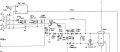
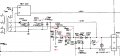
Here is a picture of the circuit. It's the 3 transistors on the top-right corner:

WP_20141026_005.jpg

Thanks in advance for your help.

...

Edit: removed the second case concerning the power supply
 
Last edited:

MrChips

Joined Oct 2, 2009
30,706
I go by finger touch. If it's too hot to touch then it's running too hot.

That board looks toasted. Not a good sign. No circuit should run that hot to cause that amount of discoloration.
The photo is not clear but it looks like a charred component between R855 and R856.
 

Thread Starter

adam555

Joined Aug 17, 2013
858
I also thought it couldn't be any good; but I don't know if the guy who sold it to me had a problem and fixed it, if he fixed it and now it's back, or if the problem has always been there. In any case you can't touch TR857 for longer than a couple of seconds; it's the one that reaches almost 70 C in just a minute after turning it on.

The component you are referring to is an inductor. It looks that way because it's in vertical position. I reality it doesn't look that bad, and it's also not too hot.

I have the schematic (I've attached that part below) and I tried to measure voltages in a few places -including the CRT BIAS pot- but couldn't find anything wrong.

I'm glad you answered because I know you are pretty good at this. :) I wouldn't even know how to continue testing it...
 

Attachments

MrChips

Joined Oct 2, 2009
30,706
See if you can locate R859, 220Ω. You might be able to measure its resistance in-circuit (WITH THE POWER OFF).

Measure the voltage across R859. This should be about 4V.
 

studiot

Joined Nov 9, 2007
4,998
The 125C refers to the chip temperature, not the case temperature.

A small component with a case temperature of 75C is likeky to be running at a chip temperature 95C - 105C, and you are getting (too) close to maximum.

At these temperatures rediffusion causes steady loss of gain, which means the transistor has to work harder (generate more heat) and is caught in a viscous circle.

If you take those three transistors out, and test them, I expect thay have gone low gain by now.
 

Thread Starter

adam555

Joined Aug 17, 2013
858
Thanks MrChips. There was an old thread where you initially helped me with the problem: http://forum.allaboutcircuits.com/t...just-did-something-strange.91663/#post-668456

I confirmed that R859 is 220Ω and the voltage across it is 3.86v.

However, when measuring the voltage at the right of R859, which should be 125v, I got 133v.

I'm also attaching the schematic that includes the CRT BIAS pot; which was on a separate page. Measured the voltages around the pot, and they seem to be fine (+75v and +8v).
 

Attachments

Thread Starter

adam555

Joined Aug 17, 2013
858
The 125C refers to the chip temperature, not the case temperature.

A small component with a case temperature of 75C is likeky to be running at a chip temperature 95C - 105C, and you are getting (too) close to maximum.

At these temperatures rediffusion causes steady loss of gain, which means the transistor has to work harder (generate more heat) and is caught in a viscous circle.

If you take those three transistors out, and test them, I expect thay have gone low gain by now.
Thanks, I'll do as you suggest.

Do you think this might have been caused by another faulty component that lead those transistors to overheat, or is it common for transistors to fail in this way after many years of use?

I'm asking because I'm concerned about changing the transistors and continue having a problem.
 
Last edited:

Thread Starter

adam555

Joined Aug 17, 2013
858
I took TR853 and TR854 off (the 2 on the top right corner) and measured the beta. The datasheet states 140 to 280, so they seem to be fine; the first with 255 and the second with 206.
 

studiot

Joined Nov 9, 2007
4,998
Di you also measure the leakage of the transistors?

But the fault it would certainly seem to lie somewhere else.
Overheating is caused by excess current being drawn somewhere, if the basic design was sound (Hitachi is a good make) and the ventilation has not been obstructed.
So it is basically a hunt for what is drawing/causing the extra current.
Resistors can go low causing extra current to be draw
Capacitors, especially electrolytics can go high leakage
You have noted a high voltage rail.
I have seen this assoicated with overheated components in scopes, especially where components are used near their voltage limits, as they often are.
 

Thread Starter

adam555

Joined Aug 17, 2013
858
Thanks,

This weekend I'll try to measure as many voltages as I can around that area; specially across resistors and electrolytic capacitors.

I don't know how to measure the leakage of a transistor. Would I have to take them out again?

By the way, I noticed that where I got 133v instead of 125v it states "+125v unregulated"; so I'm not sure what to make of it.
 

MrChips

Joined Oct 2, 2009
30,706
Sorry, I have not been able to give attention to your oscilloscope.

3.87V across R859 is the expected value. Hence the current draw is within expected value.

The total power drawn by that section of the circuit is 17.6mA x 125V = 2.2W

My guess is that that should not be a problem. Most of that power is dissipated across TR853, R857, TR851
and TR852, R858, TR854, 1.1W for each side of the horizontal driver.

I would not worry about 133V as opposed to 125V.

I would leave that section alone for now and try to look at the brightness issue.
Sorry, it will be another day before I have the time to look into the problem.
 

Thread Starter

adam555

Joined Aug 17, 2013
858
Thanks. No hurries; I can still use it without the cover.

I've been checking as many voltages as I could, and all of them seem to be fine; except the 132v, which come out directly, and unregulated, from the main transformer after a half wave rectifying diode and filtering cap.

I've also been looking at the area that deals with the brightness; instead of the top right corner, which deals with X axis. But I also can't find anything wrong; though I don't have the tools to measure some of those high voltages:

 
Last edited:

MrChips

Joined Oct 2, 2009
30,706
When you say adjusting the pot has no effect, which pot are you referring to, RV1021 CRT BIAS or RV1301 INTENSITY?


Thread Starter

adam555

Joined Aug 17, 2013
858
I'm referring to the RV1021 CRT BIAS pot. It should control the maximum brightness that you can adjust with the RV1301 intensity knob, but now it only adjusts it to certain point and going any further has no effect. In fact, if you pass that point (on the CRT BIAS) you can adjust the intensity knob up to a certain brightness, and then the further you go up, the further the intensity drops.

This didn't happen when it was working well; you where able to set the CRT BIAS to whatever maximum brightness you liked -it could go quite high actually- and then control it with the intensity knob.

I'm attaching a schematic with what I've done so far: I wrote the voltages I measured and marked the resistors I checked in red. Everything seems to be fine.
 

Attachments

Thread Starter

adam555

Joined Aug 17, 2013
858
I'm not sure, but I think there's something wrong with the CRT BIAS pot itself; which was the component causing the problem last time.

When I measure the voltage it seems to be fine -that's why I didn't suspect before-; I read from 8v to 75v on the center pin. But with the oscilloscope off, when I measure the resistance between the bottom pin and the middle pin, I only read from 0 ohm to 32k up to the middle, and from the middle again down to 8k. Shouldn't it read from 0 to 100k?
 

MrChips

Joined Oct 2, 2009
30,706
If you measure the pot while in-circuit you could get misleading results depending on the resistance of the rest of the circuit, i.e. at the power supply.
You would have to disconnect two of the three connections to get accurate results.

I am thinking the fault lies in the circuit around TR901-TR912.

Are you able to measure the voltages at R915 while you adjust the INTENSITY pot?
 

Thread Starter

adam555

Joined Aug 17, 2013
858
With the intensity knob at minimum I read on R915:
- 5.5v on the left side and 5.4v on the right side, both with respect to ground.
- and 53mV across.

With the intensity knob at maximum I read:
- 49.1v on the left and 48.8 on the right
- and 354mV across.

I also confirmed it's 220 ohm
 

Thread Starter

adam555

Joined Aug 17, 2013
858
I am thinking the fault lies in the circuit around TR901-TR912.
I just finished measuring all the resistors and voltages in that area; but I can't tell if there's anything wrong with it.

I'm attaching a file with the measurements. The resistors in a circle gave me a different reading than expected; I marked them just in case. The voltages with 2 values divided by '/' are for the intensity knob at minimum and maximum. And the voltages between parenthesis are the voltages across a component.
 

Attachments

MrChips

Joined Oct 2, 2009
30,706
Nice work. I will study it over.

Of course you know that measuring resistances in-circuit could give you incorrect results.
 
Top