Facebook
 Google
 GitHub
 Linkedin
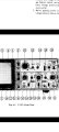
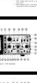
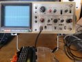
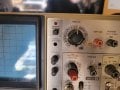
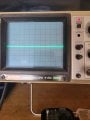
I noticed the device operates between 1.8-5.5 volts. That is fine by me. I can keep the voltage in that range.The Hitache V-212 oscilloscope has a bandwidth of 20MHz and will be ideal for the TS application. A modern digital oscilloscope with FFT capability is a very expensive tool. I made my own audio spectrum analyser using a ATMega328 microcontroller with a 1.7" OLED color display.
Hitachi Oscilloscope V-212 testing question
- Thread starter Automan350
- Start date