High Voltage regulator 175V input to 163V

Thread Starter

artmaster547

Joined Jan 6, 2016
409
Hi all
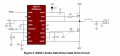
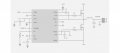
I am looking for a high voltage regulator that will take in 175V and output 163V output current between 0.5A and 1A, I'm looking for something similar to the TI TL783C, which doesn't quite have the output voltage but something similar to this would be perfect.

Kind Regards

Jonathan
 

ElectricSpidey

Joined Dec 2, 2017
3,334
From the data sheet...

Besides replacing fixed regulators, the LM117 is useful in a wide variety of other applications. Since the regulator is “floating" and sees only the input-to-output differential voltage, supplies of several hundred volts can be regulated as long as the maximum input to output differential is not exceeded, i.e., avoid short-circuiting the output.
 

dendad

Joined Feb 20, 2016
4,637
If you do not use a reg that can handle the full volts, there is a chance of much smoke on turn on and as ElectricSpide says, short-circuiting or overload conditions. I think a switch mode buck converter would be a much safer alternative.

What is your 175V power supply and the actual load you are running?

EDIT
I was thinking of some thing like this...
https://www.aliexpress.com/item/220...4b19-4997-9910-5a5700d80199&priceBeautifyAB=0

But this is 220VAC in. If you can find a "universal input" one, you can feed the 175VDC into it and set the output to 163V.
 
Last edited:

ebp

Joined Feb 8, 2018
2,332
Without foldback current limiting that is 175 W to be dissipated in the pass device under short-circuit conditions. That is a lot of power and would require careful attention to safe operating area and thermal management. SOA with BJTs won't be easy. It is perilous to use ordinary MOSFETs as pass devices with those conditions because of the non-linear tempco of resistance of the cells. IXYS offers a limited line of MOSFETs specifically for linear applications. They are rather expensive but not obscenely so.

Nice work for a thermionic valve.
 

Dodgydave

Joined Jun 22, 2012
11,395
Just put a 50V Zener diode in the ground path of your TL783C regulator, this will shift the output by 50V, and then you can trim it down as normal with the resistors.


7805-11.png
 

dendad

Joined Feb 20, 2016
4,637
If you are going to go with the linear dropping of the voltage, you may find the series diode trick will work well enough, with an added fuse if the 175V supply does not have current limiting.
But you still have not told us details, like the use this is for, and how critical the voltage is. That could make a real difference to the final circuit.
I would advice against any circuit that has any part connected to 0V and does not have the voltage rating of well over the 175V that will appear across it on a start up surge and short circuit condition.
If you cannot put a short on the 165V out without destroying your circuit do not use it!
 

Thread Starter

artmaster547

Joined Jan 6, 2016
409
If you are going to go with the linear dropping of the voltage, you may find the series diode trick will work well enough, with an added fuse if the 175V supply does not have current limiting.
But you still have not told us details, like the use this is for, and how critical the voltage is. That could make a real difference to the final circuit.
I would advice against any circuit that has any part connected to 0V and does not have the voltage rating of well over the 175V that will appear across it on a start up surge and short circuit condition.
If you cannot put a short on the 165V out without destroying your circuit do not use it!
Hi sorry what I really need is -163V was thinking of getting working that did 175V to 163V and just changing the reference to GND, I need this voltage for a class D amplifier half bridge driver Si824x (Si8241) the reason I need this large negative voltage is because I am switching the half bridge between +175V and -175V, but the boostrap circuit used for this driver needs a negative voltage that is 12V higher than the lowest voltage i.e. -175V +12V =-163V
 

dendad

Joined Feb 20, 2016
4,637
Well, in that case, all you need is a 12V zener with a cap across it, and a resistor.
maybe a 15K resistor from 0V to -163V, and the 12V zener from -163V to -175V.
The bootstrap supply is not a real high current.
Can you post a circuit?

Is this about the way you are doing it?
Si8241_cct1.jpg

The values are a bit of a guess. A 1W 15K resistor is needed, or higher if you lower the resistance.
 
Last edited:

Thread Starter

artmaster547

Joined Jan 6, 2016
409
Well, in that case, all you need is a 12V zener with a cap across it, and a resistor.
maybe a 15K resistor from 0V to -163V, and the 12V zener from -163V to -175V.
The bootstrap supply is not a real high current.
Can you post a circuit?

Is this about the way you are doing it?
View attachment 148840

The values are a bit of a guess. A 1W 15K resistor is needed, or higher if you lower the resistance.
Yeah the current was the one thing I was not sure about this is an example that Silicon labs have provided (Combo of the image and eval kit datasheet) which is what I was going to base it off, they used a regulator in the eval kit (PDF attached) to generate the negative voltage which is why I went down that route.
 

Attachments

dendad

Joined Feb 20, 2016
4,637
I think the zener and resistor will work ok.
A 15K 1W resistor will give about 11mA zener current. If that is not enough, just add extra 15K resistors in paralell with the original. If you use a 1W zener, you could up to 80mA through the zener but I would aim lower.
 

Thread Starter

artmaster547

Joined Jan 6, 2016
409
I think the zener and resistor will work ok.
A 15K 1W resistor will give about 11mA zener current. If that is not enough, just add extra 15K resistors in paralell with the original. If you use a 1W zener, you could up to 80mA through the zener but I would aim lower.
ok great that solves a lot of problems in a simple way thanks for your help :)
 

Thread Starter

artmaster547

Joined Jan 6, 2016
409
I think the zener and resistor will work ok.
A 15K 1W resistor will give about 11mA zener current. If that is not enough, just add extra 15K resistors in paralell with the original. If you use a 1W zener, you could up to 80mA through the zener but I would aim lower.
just to confirm the schematic you drew up carries out the same function in this image?
 

Attachments

dendad

Joined Feb 20, 2016
4,637
All amps and actually most ICs should have caps across the power supply to 0V.
The isea is to give a low impeadance to noise on the power rails due to pulses of current drawn by the device. Your power supply would have the caps in it but some more as close to the amp as can be is a good idea. A value could be 220uF 450V and they can be rescued out of old PC power supplies. It would be a good idea to test them first.
I don't remember how to calcUlate the values based on the current etc but those or something like it will be ok.
 

Thread Starter

artmaster547

Joined Jan 6, 2016
409
All amps and actually most ICs should have caps across the power supply to 0V.
The isea is to give a low impeadance to noise on the power rails due to pulses of current drawn by the device. Your power supply would have the caps in it but some more as close to the amp as can be is a good idea. A value could be 220uF 450V and they can be rescued out of old PC power supplies. It would be a good idea to test them first.
I don't remember how to calcUlate the values based on the current etc but those or something like it will be ok.
ok sure thank you
 

Thread Starter

artmaster547

Joined Jan 6, 2016
409
All amps and actually most ICs should have caps across the power supply to 0V.
The isea is to give a low impeadance to noise on the power rails due to pulses of current drawn by the device. Your power supply would have the caps in it but some more as close to the amp as can be is a good idea. A value could be 220uF 450V and they can be rescued out of old PC power supplies. It would be a good idea to test them first.
I don't remember how to calcUlate the values based on the current etc but those or something like it will be ok.
Do you know where I could go to find out this calculation for capacitors for other designs I may make?
 
Top