Facebook
 Google
 GitHub
 Linkedin
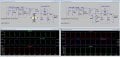
Thanks !!.... First experience with LT Spice. Though C was defaulted to pF... i'll correct and add the scope probe 10:1 which I forgot to.hi p,
The single diode is upside down, refer to my earlier sim image. [other thread]
Eric
PS:
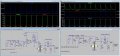
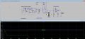
See my post on your other thread regarding Cap values, you show all in Farads!!
Whats the LT Spice equivalent of a 10:1 ratio probe?
Which TVS would you advise?
Last edited by a moderator:
")