High voltage capacitive pick up and input protection circuit

Thread Starter

patpin

Joined Sep 15, 2012
401
Hello,
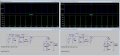
I am working on a capacitive pickup probe as:
upload_2016-3-2_15-13-56.png

As mentioned the 1000µF has to be 1000pF. This gives a reduction of 100:1 (measuring on 3KV --> 30V).
I would like to see the waves with a Bitscope BS05.
I plan to connect a scope probe with a second reduction 10:1 and so input signals will be in the range of 3V.
BUT if a spark is jumping over from the sparkplug wire to the probe, it could destroy the BS05 and possibly the PC hanging on it over USB.
I read some things about high voltage protection in combination with differential op amps here:
https://www.maximintegrated.com/en/app-notes/index.mvp/id/5724
where the author also mentions neon lamps and clipping circuits with zeners etc.
It seems this is also useful: https://datasheets.maximintegrated.com/en/ds/MAX13202E-MAX13208E.pdf
Anybody has experience with such a input protection circuits and dimensioning them?
Anyone uses this MAX serie in combination with classic input protection circuits?
 

Attachments

Last edited:

MrAl

Joined Jun 17, 2014
11,389
Hi,

The main thing is to provide enough impedance between the node point and the clamp so that it does not load the node point.
The secondary thing is that for a circuit that can ring positive and negative you need a clamp that can clamp either plus or minus overshoots. Two zeners connected in anti parallel perhaps, or high speed diodes.
The series resistance should probably be several resistors in series to make up one total resistor. Regular resistors are not rated for very high voltages, but in series the combination can handle higher voltage.
Say five 200k resistors in series to start with, all connected in one physically straight line. It's hard to say what the exact value should be.
It might also help to know the value of the capacitance of the 'capacitance probe' or see the physical construction.
 

Thread Starter

patpin

Joined Sep 15, 2012
401
Hi,

The main thing is to provide enough impedance between the node point and the clamp so that it does not load the node point.
The secondary thing is that for a circuit that can ring positive and negative you need a clamp that can clamp either plus or minus overshoots. Two zeners connected in anti parallel perhaps, or high speed diodes.
The series resistance should probably be several resistors in series to make up one total resistor. Regular resistors are not rated for very high voltages, but in series the combination can handle higher voltage.
Say five 200k resistors in series to start with, all connected in one physically straight line. It's hard to say what the exact value should be.
It might also help to know the value of the capacitance of the 'capacitance probe' or see the physical construction.
for the physical construction and capacitance i refer to http://www.lotuselan.net/forums/download/file.php?id=9946
In this article they say it is 1pF.
The clamp is at a distance of about 4mm from the center of the sparplug wire and consists of a split tube of about 4cm glued in a clothing peg, It is however known that in the case of a bad sparkplug or another interruption of the normal path (open spark line), the high voltage can rise to 8KV or more and the spark can fire over a 1cm gap...
Thats is why I thought using a good clipping network as you can see in the next post.
 
Last edited:

Thread Starter

patpin

Joined Sep 15, 2012
401
upload_2016-3-2_18-25-52.png. This diagram comes from the first link of this tread, where designers wanted to protect a ECG device from a 5KV pulse. In our case the ampli following Rl is not necessary.
How can one dimension such a network?
 
Last edited:

Thread Starter

patpin

Joined Sep 15, 2012
401
This diagram above comes from the first link of this tread, where designers wanted to protect a ECG device from a 5KV pulse. In our case the ampli following Rl is not necessary.
How can one dimension such a network? What is SW1 D4 D5 and the unconnected TVS?
 

MrAl

Joined Jun 17, 2014
11,389
Hi,

The TVS is probably an alternate suggestion, or else it is there to shunt any ghosts that might appear at the input to ground :)

The TVS seems like a good idea. One that limits to say 170v and then another series resistor, then two zeners, then another resistor, then two diodes.

The main problem then is to figure out how much power that 8kv signal can deliver.
One thing we dont want to happen is the TVS burns out after a few uses, then there's less protection.
A series resistor first would limit the energy to the TVS, so we could probably just size it according to that requirement. For example, if the TVS is 200v and has a 1k resistor and a 8200v pulse signal comes along that lasts for 5ms, the peak energy in the TVS would be 8 Joules. A thermistor could monitor the temperature of the TVS to see if it gets hot at any point for safety. Of course two TVS's in parallel cant hurt either.

How many cylinders is the engine?
 

Thread Starter

patpin

Joined Sep 15, 2012
401
Hi,

The TVS is probably an alternate suggestion, or else it is there to shunt any ghosts that might appear at the input to ground :)

The TVS seems like a good idea. One that limits to say 170v and then another series resistor, then two zeners, then another resistor, then two diodes.

The main problem then is to figure out how much power that 8kv signal can deliver.
One thing we dont want to happen is the TVS burns out after a few uses, then there's less protection.
A series resistor first would limit the energy to the TVS, so we could probably just size it according to that requirement. For example, if the TVS is 200v and has a 1k resistor and a 8200v pulse signal comes along that lasts for 5ms, the peak energy in the TVS would be 8 Joules. A thermistor could monitor the temperature of the TVS to see if it gets hot at any point for safety. Of course two TVS's in parallel cant hurt either.

How many cylinders is the engine?
Hello,
Indeed TVS's can destroy 2 ways - closed or open which is worse. The idea of a temp sensor is interesting!
Motor: n° of cylinders: 12; but I pick up the signal at cyl 1 for triggering and then at coil to distributor line for a inspection of all cylinders
Both probe lines should be protected
Where should I put the TVS in the chain of
1/ clamp on pickup probe (100:1 capacitive)
2/ scope probe (10:1 probably resistive; is a classic scope probe)
3/ Bitscope
What Ppp Vvm Vc would you consider in such a case?
 

MrAl

Joined Jun 17, 2014
11,389
Hi,

The first resistor would go in series with the pickup, then the TVS from that resistor to ground. After that, another resistor and two zeners probably back to back, to catch transients of either polarity.
Any scope probe would connect to the top of the zeners, or if you use back to back diodes then to the top of those diodes.

The highest voltage i have ever done something like this with was about 300v. I had to measure the transistor saturation voltage of a switching transistor in order to estimate the total power usage. The scope had to be set at a low enough voltage to read sat voltages around 2v maybe less, so i needed a resistor and clamp. I cant remember what the value of the resistor was though. The main thing is to size it so that the clamping device does not dampen the response or of course clamp the desired signal to be measured. So that was resistor plus zener (no danger of reverse polarity there though).

So one of the things you'll have to measure is the resistance of the TVS, and it would be best to do a test to make sure the desired signal can get through undistorted, perhaps with a wave generator.

Some questions...
What is the expected bandwidth of the signal to be measured?
I am not that familiar with 12 cylinder engines. Do the plugs fire sequentially or do they fire in pairs?
Do you happen to know the base frequency of the pulsing from the coil?
It would be best if you dont use too many abbreviations. What is Ppp, Vvm, and Vc ?
 

Thread Starter

patpin

Joined Sep 15, 2012
401
Hi,

The first resistor would go in series with the pickup, then the TVS from that resistor to ground. After that, another resistor and two zeners probably back to back, to catch transients of either polarity.
Any scope probe would connect to the top of the zeners, or if you use back to back diodes then to the top of those diodes.

The highest voltage i have ever done something like this with was about 300v. I had to measure the transistor saturation voltage of a switching transistor in order to estimate the total power usage. The scope had to be set at a low enough voltage to read sat voltages around 2v maybe less, so i needed a resistor and clamp. I cant remember what the value of the resistor was though. The main thing is to size it so that the clamping device does not dampen the response or of course clamp the desired signal to be measured. So that was resistor plus zener (no danger of reverse polarity there though).

So one of the things you'll have to measure is the resistance of the TVS, and it would be best to do a test to make sure the desired signal can get through undistorted, perhaps with a wave generator.

Some questions...
What is the expected bandwidth of the signal to be measured?
I am not that familiar with 12 cylinder engines. Do the plugs fire sequentially or do they fire in pairs?
Do you happen to know the base frequency of the pulsing from the coil?
It would be best if you dont use too many abbreviations. What is Ppp, Vvm, and Vc ?
Thank MrAI, I'll try to make a diagram today.
The firing orrurs every two revolutions of the crankshaft and sequentially. A few examples:
RPM 800 (idle)
cylinders 12
firing freq 80 per sec

RPM 3000 (max RPM for test session)
cylinders 12
firing freq 300 per sec

in a doc on TVS params http://www.microsemi.com/document-portal/doc_view/14650-how-to-select-a-transient-voltage-suppressor
I read that those are the most important selection params:
- the Rated Working Peak Voltage or Rated Standoff Voltage (Vwm),
- voltage Vbr. It is typically 10 to 15% above Vwm and is the voltage that TVS devices go into avalanche similar to a zener diode
- Vc or clamping voltage under high-current pulse conditions. It is typically 35 to 40 % higher than VBR (or 60 % higher than VWM
) and represents the maximum clamping voltage during the specified peak impulse current Ipp
-Ppp is the power dissip at Ipp
 

MrAl

Joined Jun 17, 2014
11,389
Hello again,

Since we are dealing with a possible 8kv we have to pay attention to the rating of the series resistors too.
Standard 1/2 watt resistors might handle up to 300v. To get to 3000v that would require 10 in series,
to get to 6000v would require 20 in series, and to get to 9000v requires 30 in series. Alternately you could look for special higher voltage resistors. When connecting them care has to be used to avoid spark over if the string is folded back on itself, leaving enough spacing between any two points.

What is the engine speed(s) that will be used for testing over the life of the device? That sets the pulse time.

Another idea is to create a corona gap. The gap would provide a shunt to ground if a spark over did occur.
The simplest would be to use a spark plug, with screw threads grounded and main pole connected to the pickup sleeve. The plug could be the same as the type used in the engine, but with the gap set to maybe 1/3 of the required gap for that car. If the voltage gets high enough, the plug will arc over and thus lower the voltage. We could look into spark gaps for more information on this too.

To get a better feel for high voltage in general, you could look into making your own scope high voltage probe. Various techniques would be found. The difference here is just that we dont need a linear response we want a clamping action, so we can ignore the details about getting the right attenuation factor and the like.

Yes, the temperature monitor would monitor the temperature of the TVS to make sure we are not getting too many repeat events. Too many over too short a time will overheat the TVS and cause big problems maybe even burn out the TVS or melt the plastic case or another part. That is, unless you want to use it as a room heater as well as specialized probe :)

As you are noting already, high voltage circuits have special characteristics that we dont see in most circuits that run on something like 12 volts. The people who would know the most about this are those that work with high voltage power supplies or other devices that are used at high voltages. Most of my practical experience lies in the 500v or less power conversion field so i have to really think to stretch into the thousandths of volts. The only nice thing is it is usually low current whereas power conversion usually deals with 10's of amps or more.
Probably the most important difference deals with the distances ... distances between neighboring objects. At 12v we need little distance between two circuit traces, but at even 2000v we need much more distance.
 
Last edited:

Thread Starter

patpin

Joined Sep 15, 2012
401
What is the engine speed(s) that will be used for testing over the life of the device? That sets the pulse time.
I will test at 800 and 3000 RPM (acceleration test) . but I also want to see the small resonance waves following the pulse from the secundary of the coil as seen in previous posts. I' have to consider that to in case I make a kind of a low pass filter.

The corona gap is een excellent idea. I can make it a tenth of a mm eg with an old sparkplug or another direct way since a sparkplug has a build in resistance (for RFI prevention) of a few K's, which is undesirable in this case..
I might think of making the probe with a second wire to earth but separated from the probe itself by a gap of 1/10mm (a plastic sheet eg). But that can probably alter the capacitance of the probe estimated in the article at 1pF. So this could reduce the 100:1 capacitive ratio but this is in fact no problem I guess.
Thanks for yr idea's!!
 
Last edited:

Thread Starter

patpin

Joined Sep 15, 2012
401
A first diagram. How would U dimension R's D Z TVS? I still have a problem with a diode avalanching to the USB +. What do U think?

upload_2016-3-3_14-38-50.jpg
 

MrAl

Joined Jun 17, 2014
11,389
Hi,

Scott:
Very nice, that makes it much easier on mobile users too...less data to download.

patpin:
I will be able to look at this more tomorrow morning, but i see you dont have any resistance between the 'probe sensor' and the TVS. Some there would limit the power to the TVS and also stop from shunting the power needed for the engine itself. Probably dont want the engine to stall during the tests :)

I saw some pretty nice resistors, not sure if we need them, but the are the 'high pulse voltage' type, which can handle 10000 volts. I'd still use at least two though.
 

Thread Starter

patpin

Joined Sep 15, 2012
401
Hi,

patpin:
I will be able to look at this more tomorrow morning, but i see you dont have any resistance between the 'probe sensor' and the TVS. Some there would limit the power to the TVS and also stop from shunting the power needed for the engine itself. Probably dont want the engine to stall during the tests :)

.
Hi MrAI, Thanks for looking at it. btw there is a 4mm gap between the HV and the TVS. If the coil fires to the pick up probe this will only cause a misfire on 1 cylinder, so the motor wont stall, but it would be an extra current limitation of coarse. It would also alter the probe ratio of 100:1 I guess, but so will do the other resistors after the TVS We will have to calibrate it...o_O.
 

Thread Starter

patpin

Joined Sep 15, 2012
401
I also got a suggestion for a circuit from eric and worked on it with spice.
I include the SIM below. It would be interesting to look for the best of both suggestions for solving the input protection problem...
If I can thrust the SIM below, I would not need any other resistances. Glad to hear some tips especially about selecting the right componant (specifications) and discussing the need for TVS's and/or neons as in post #4.
 

Attachments

Last edited:

ericgibbs

Joined Jan 29, 2010
18,766
ESD protection I guess. Many protections are in parallel as in #4 for the very sensitive ECG
hi p,
The single diode is upside down, refer to my earlier sim image. [other thread]
Eric

PS:

See my post on your other thread regarding Cap values, you show all in Farads!!
 

Attachments

Top