High side N channel mosfets explode

Thread Starter

Rivera25081

Joined Aug 8, 2013
8
Hi guys, im new to this forum, so i will introduce myself im an electronics engineering student.

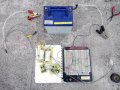
im having this problem with this n channel mosfet H bridge, the mosfets are the irf1407,
im trrying to drive a 12 volts 14 amps motor.

when i start the circuit, the motor runs fine i let it work for about 1 minute (im using Q1 and Q4), it draws 12 amps
so the motor is not the problem, the problem is when i want to change to rotation of the motor
so i start using the other two mosfets, Q2 and Q3, it takes me about 10 seconds to this as soon as i start
the circuit, Q1 explodes, the same thing happens if i do it the inverse way, i start using Q2 and Q3 and
when i change the rotation Q2 explodes. Im using the p600g as flyback diodes.

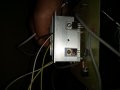
i have noticed a few things, although voltage or current dont fall Q1 and Q2 are always
hotter than Q3 and Q4 , when the mosfets explode
it is always the gate the parte that suffers most of the damage.

unfortunately im not allowed to use any driver IC.

i am thinking that probably driving the mosfets with 50 volts isnt a good idea, since i´ll get the spare
transistors until tomorrow i cant run any tests for today or maybe my circuit is not well designed.
thanks guys any suggestion or advice is welcomed.
 

Attachments

crutschow

Joined Mar 14, 2008
38,505
Yes, typically the gate-source voltage of a MOSFET should be no more than 20V.
This value is given in the data sheet as an Absolute Maximum.

Are you turning off all transistors and allowing the motor to stop before you reverse it?
You should, otherwise the high current required by the motor for the sudden reversal could damage the transistors
 

AlbertHall

Joined Jun 4, 2014
12,625
Q1 and Q2, when fully switched on, the source will be at the supply voltage. To achieve this, the gate must be at a voltage above the supply voltage. This circuit cannot do that, so Q1 and Q2 will never reach saturation. they will be passing lots of current with lots of voltage across them, dissipating lots of power and getting hot.

You need to use P-channel devices for Q1 and Q2 then they can be saturated by pulling the gate down to 0V.
 

Thread Starter

Rivera25081

Joined Aug 8, 2013
8
Yes, typically the gate-source voltage of a MOSFET should be no more than 20V.
This value is given in the data sheet as an Absolute Maximum.

Are you turning off all transistors and allowing the motor to stop before you reverse it?
You should, otherwise the high current required by the motor for the sudden reversal could damage the transistors
yes i am disconnecting the battery and after more or less 10 seconds connect the battery and reverse it, another thing i forgot to mention is that is happens only when im using the motor but if a use a resistive load the cicuit reverses the voltage with no problem
 

Thread Starter

Rivera25081

Joined Aug 8, 2013
8
Q1 and Q2, when fully switched on, the source will be at the supply voltage. To achieve this, the gate must be at a voltage above the supply voltage. This circuit cannot do that, so Q1 and Q2 will never reach saturation. they will be passing lots of current with lots of voltage across them, dissipating lots of power and getting hot.

You need to use P-channel devices for Q1 and Q2 then they can be saturated by pulling the gate down to 0V.
i can only use N channel mosfets, i have noticed that the ouput voltage is about .9 volts lower than the supply voltage all the time so may be thats why the high side transistors heat but i havent found a way to solve this, may be a resistance that goes from gate to source(in the high side mosfets) besides de 10k that goes to ground will help.

or maybe a should use 1k resistance to ground so that the mosfet will go off faster
 

Alec_t

Joined Sep 17, 2013
15,119
As Albert said in post #4, "the gate must be at a voltage above the supply voltage.". Research "high-side n-channel mosfet driving" to see how that can be achieved.
 

Thread Starter

Rivera25081

Joined Aug 8, 2013
8
As Albert said in post #4, "the gate must be at a voltage above the supply voltage.". Research "high-side n-channel mosfet driving" to see how that can be achieved.
so those 50 volts are destroying my mosfets, when i measure G-S it is 38 volts int the high side mosfets and 50 in the low side
 

jpanhalt

Joined Jan 18, 2008
11,087
You are fighting physics, and physics will win. N-mosfets in a high configuration require a gate supply of higher voltage than the voltage attached to the drain.* If you can't use a commercial driver, can you make your own? Can you use a microcontroller or oscillator to boost the voltage?

John

*That applies to the mosfets you have chosen. There are/were integrated N-channel mosfets that include a driver built in. One example is the IPS5551T, which may not be readily available from usual component suppliers today.
http://www.irf.com/product-info/datasheets/data/ips5551t.pdf
https://www.amazon.com/1PCS-IPS5551T-MOSFET-100A-IPS5551/dp/B017SBKXDC
 

Thread Starter

Rivera25081

Joined Aug 8, 2013
8
thanks, so ive been killing my mosfets by exceding their max G-S volts, the part i dont understand is why they work propperly until i reverse the voltage with the motor connected
 

Thread Starter

Rivera25081

Joined Aug 8, 2013
8
guys thanks for the help I solved the problem, it was driving the mosfets with voltage too high, Im doing it now with 26 volts i know it is a little high but it is working now, it inverts the voltage propperly and the mosfets baley heat( even though the motor is driving 30 amps), thanks guys

some photos of the final work, i know it looks like a mess but we are working to solve the aesthetic problems.
 

Attachments

Top