High side discrete mosfet driver

crutschow

Joined Mar 14, 2008
38,936
.............................
Another problem:

A am only getting a maximum of 7.7V on the output (10% of duty cicle = inverted to 90%). Is there a way the increase this?
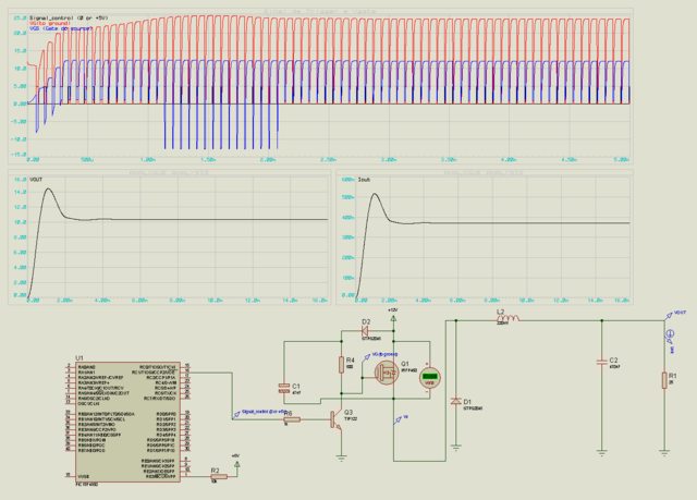
You should be getting about 10V. Post the waveforms as you did for the 50% duty-cycle case.

P.S. Why are you using the large, slow TIP122 darlington for the driver transistor? Much better to use a faster small switch such as the 2N3904 as shown in Audio Guru's circuit.

Also the IRFP460 has a rather high ON resistance of 0.27Ω. A device with a lower ON resistance would be more efficient and give a higher output voltage for a given duty-cycle and load.
 

Thread Starter

MatheusLPS

Joined Jul 16, 2011
34
You should be getting about 10V. Post the waveforms as you did for the 50% duty-cycle case.
You are right. On the simulation, I am getting ~ 10V. The problem is with the circuit on the protoboard. Look:


P.S. Why are you using the large, slow TIP122 darlington for the driver transistor? Much better to use a faster small switch such as the 2N3904 as shown in Audio Guru's circuit.
The problem is that I do not have so many transistor with me and since it is weekend, I can not buy anything now. :D

Searching my on my box, I found a BD135, some BC's... a lot of TIPs

EDITED:

Just found a 2N3904 laying on the last box of components..... wow... Changing the TIP122....

Also the IRFP460 has a rather high ON resistance of 0.27Ω.
Same thing as said before. Most of my FETs are found on old power supplies....

I have others and will check for a lower RDs ON.

EDIT:

Forgot to mention that on the simulation i am using a 220uH inductor. But on the protoboard, I am using a inductor took from a power supply. Do not know the value. Ferrite core.

thanks
 
Last edited:

Alec_t

Joined Sep 17, 2013
15,163
The inductor properties are critical in switch-mode circuits. The wrong inductance or core properties can lead to core saturation, which is a no-no.
 

Thread Starter

MatheusLPS

Joined Jul 16, 2011
34
The inductor properties are critical in switch-mode circuits. The wrong inductance or core properties can lead to core saturation, which is a no-no.
Thanks for the info. This one is just a prototype. With the final circuit, I will buy the right inductor.

So. Changed the TIP122 with the 2N3904 and replaced the IRFP460 with the CEP51A3: http://pdf1.alldatasheet.net/datasheet-pdf/view/176714/CET/CEP51A3.html

Improved. Getting now 9.3V at output. I using a potentiometer to change the duty cicle. Can change from 0V to 9.3V.

Now, I need to check the waveforms with a oscilloscope. But, only next week.

bye
 
Top