 Facebook
 Google
 GitHub
 Linkedin
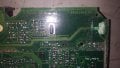
I have a question about an ECM I am working on. The unit took on some water and as you can see from the picture, it corroded a terminal at the end of a very large capacitor. I have this board repaired but now when I turn it on, there is a constant high pitched squeal coming from the large inductor/capacitor area and I can't put my finger on it. The connection point is also the hottest point on the board at around 155 degrees while the rest of the board idles around at about 70 degrees. Does this sound normal or do I need to go do some more digging. I have no schematics to go by. I am sure this is part of the power supply for this board so would it generate a lot of heat? Does this type of cap have reason to squeal?
The repair has been done properly. I laid a large copper contact over the area, soldered it to the capacitor and both legs coming into it and epoxied it to the board. There are no more codes being set by this unit so that part is cured. The code it had before was a power issue.
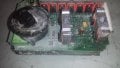
The large green cap is 14uF and the large black unit is the inductor.
Cheers
The repair has been done properly. I laid a large copper contact over the area, soldered it to the capacitor and both legs coming into it and epoxied it to the board. There are no more codes being set by this unit so that part is cured. The code it had before was a power issue.
The large green cap is 14uF and the large black unit is the inductor.
Cheers
Attachments
-
 226.6 KB Views: 36
 -
 219.5 KB Views: 36
 -
 97 KB Views: 35
 .
.


