Facebook
 Google
 GitHub
 Linkedin
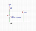
As I stated above, my plan was to try a smaller photodiode, in order to increase the sensitivity. The project was for a capture to trigger a screen to freeze on an instrument when light was present. R1 value was 50K and no r2-open collector. I never ordered another diode, but I got it to work using a 600um fiber instead of 400um. Not sure of the light intensity. It seems that the sensitivity is proportional to the resistance of R1, but if I use too much resistance my "zero" ohms condition creeps higher across the collector/emitter.
For now, what i have is sufficient, but I will continue to try and improve the design. With regard to speed and sensitivity, I'd love to have a formula to be able to know what is going on. I'm somewhat "in the dark" when it comes to photodiodes and dark current. I'm assuming the resistance/impedance of the diode is dependent on the amount of light the diode sees. More light pulls more of the current to ground increasing the resistance across collector/emitter as it shuts off the transistor?
thanks again for all of the replies.
For now, what i have is sufficient, but I will continue to try and improve the design. With regard to speed and sensitivity, I'd love to have a formula to be able to know what is going on. I'm somewhat "in the dark" when it comes to photodiodes and dark current. I'm assuming the resistance/impedance of the diode is dependent on the amount of light the diode sees. More light pulls more of the current to ground increasing the resistance across collector/emitter as it shuts off the transistor?
thanks again for all of the replies.