Facebook
 Google
 GitHub
 Linkedin
any brother can help me on this..........
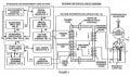
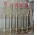
i'm doing electrolysis project to produce hydroxy, i have tried to use pwm circuit to run my experiment, the problem i face is it cannot improved the efficiency at the higher current (it can be improve when i trying a rod, 180mA improved to 220mA, When adding more rod, result will be same to direct DC supply, it's also happened when i trying on stainless steel plate). When i connect to +- plate (2 Plate) of SS plate, the current i get is 1300mA (with and without PWM) , the another problem is the fix voltage regulator MC7812C will be heat when i adding more than 2 plate of SS, anyone can give me some suggestion to modified my circuit?????
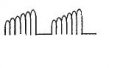
i'm heard that waveform 1 as attached as a output can improved the efficiency of the result, anyone know that it's true or not?
all picture are attached as below.......
Thanks for helping me...........brother........
hope u all can help me solve this problem.....
i'm doing electrolysis project to produce hydroxy, i have tried to use pwm circuit to run my experiment, the problem i face is it cannot improved the efficiency at the higher current (it can be improve when i trying a rod, 180mA improved to 220mA, When adding more rod, result will be same to direct DC supply, it's also happened when i trying on stainless steel plate). When i connect to +- plate (2 Plate) of SS plate, the current i get is 1300mA (with and without PWM) , the another problem is the fix voltage regulator MC7812C will be heat when i adding more than 2 plate of SS, anyone can give me some suggestion to modified my circuit?????
i'm heard that waveform 1 as attached as a output can improved the efficiency of the result, anyone know that it's true or not?
all picture are attached as below.......
Thanks for helping me...........brother........
hope u all can help me solve this problem.....
Attachments
-
 42.8 KB Views: 69
 -
 24.4 KB Views: 41
 -
 27.7 KB Views: 43
 -
 2.4 KB Views: 37