Help with unmarked Transistor in Diagram

Thread Starter

headros

Joined Feb 10, 2014
5
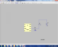
Hello, I am learning transistors and trying to make this circuit, but I have no idea what type of NPN transistor I need, or how to calculate which transistor I need. Please help! I attached an image of the diagram.
 

Attachments

#12

Joined Nov 30, 2010
18,224
2N3904 or 2N4401 or 2N2222

I find it unlikely that an LED like that will survive 100 ma at 50% duty cycle so I named 3 transistors that can carry most of an amp.
The math does show about 100 ma through the LED, but I would expect it to smoke immediately.
In addition, a 9 volt battery can not supply that quality of current for more than a few seconds.
The power burden on the transistor would be .315 watts if the circuit worked. The TO-92 plastic package transistors would probably get a bit too hot. Glue a coin to the transistor or get a TO-5 package transistor.

You are allowed to ask more questions.
 
Last edited:

burger2227

Joined Feb 3, 2014
194
Don't some IR LED's go over 100 ma with a little red glow? I wish the glow wasn't. It completely gives away cameras.

Headros, what are you jamming? :)
 

bertz

Joined Nov 11, 2013
327
Don't some IR LED's go over 100 ma with a little red glow? I wish the glow wasn't. It completely gives away cameras.

Headros, what are you jamming? :)
The HSDL-4200 series IR LED typically operate around 100 mA, but can go higher. Most general purpose NPN's (2N4401) can handle 500mA.
 

Thread Starter

headros

Joined Feb 10, 2014
5
Thank you for the responses. I popped in a 2N4401 and tested the circuit. I measured 1.4v across the IR emitter diode but the transistor temp got over 170F before i switched it off. Is this normal? Glue a penny to it?

 
Last edited:

bertz

Joined Nov 11, 2013
327
Thank you for the responses. I popped in a 2N4401 and tested the circuit. I measured 1.4v across the IR emitter diode but the transistor temp got over 170F before i switched it off. Is this normal? Glue a penny to it?
Replace the 5R6 resistor with a 100 ohm resistor and measure the collector current. You do know how to measure the 2N4401 collector current, don't you?

What is the part number of the IR LED you are using? Have you checked the data sheet to determine operating parameters?
 

ronv

Joined Nov 12, 2008
3,770
Interesting circuit. Not good, but interesting. The problem it has is that the power is dissipated in the transistor - about a half watt. So yup it gets hot. The 555 can drive 100 ma. by itself so just simplify it like the attached. Problem is it takes a 1 watt - well at least a 1/2 watt resistor.
 

Attachments

bertz

Joined Nov 11, 2013
327
Thank you for the responses. I popped in a 2N4401 and tested the circuit. I measured 1.4v across the IR emitter diode but the transistor temp got over 170F before i switched it off. Is this normal? Glue a penny to it?

Unless my eyes deceive me, you have the 1N4148 diodes in backwards (black band is the cathode). As a result, your Base-Emitter current is off the chart and that is adding to the collector current to heat up that transistor. The 2N4401 has a typical gain of around 100 so you should need less than 1 mA to saturate the transistor.

Change that 470 ohm bias resistor to 4.7k and change the current limiting resistor in the collector circuit to 100 ohm, 1/2 watt.

With that having been said, it seems to me that this is a pretty useless circuit. Most IR remote control modulates the IR signal between 34 and 40 kHz using the Sony SIRC protocol. This circuit doesn't modulate, it turns the beam on and off. Maybe that will jam a TV remote, I don't know. But you'll be playing with that pot trying to find the correct modulating frequency.

Good luck

Al
 

Thread Starter

headros

Joined Feb 10, 2014
5
Unless my eyes deceive me, you have the 1N4148 diodes in backwards (black band is the cathode). As a result, your Base-Emitter current is off the chart and that is adding to the collector current to heat up that transistor. The 2N4401 has a typical gain of around 100 so you should need less than 1 mA to saturate the transistor.

Change that 470 ohm bias resistor to 4.7k and change the current limiting resistor in the collector circuit to 100 ohm, 1/2 watt.

With that having been said, it seems to me that this is a pretty useless circuit. Most IR remote control modulates the IR signal between 34 and 40 kHz using the Sony SIRC protocol. This circuit doesn't modulate, it turns the beam on and off. Maybe that will jam a TV remote, I don't know. But you'll be playing with that pot trying to find the correct modulating frequency.

Good luck

Al
Thank you for the input Al and others, i changed the 470ohm to 4.7k, corrected the backwards diode (rookie mistake :/). The temp of the transistor is now 145F.

Then i changed the 5R6 to 100ohm and its 76F, but the voltage to the IR diode dropped to 1.2v

The specs for this IR diode are: cont. forward cur: 100mA, 1.5v typical 1.8v max @50mA, 5v reverse voltage
The final outcome is to produce a constant 38kHz signal that interferes with the signal from a remote control (supposedly).
 
Last edited:

bertz

Joined Nov 11, 2013
327
Thank you for the input Al and others, i changed the 470ohm to 4.7k, corrected the backwards diode (rookie mistake :/). The temp of the transistor is now 145F.

Then i changed the 5R6 to 100ohm and its 76F, but the voltage to the IR diode dropped to 1.2v

The specs for this IR diode are: cont. forward cur: 100mA, 1.5v typical 1.8v max @50mA, 5v reverse voltage
The final outcome is to produce a constant 38kHz signal that interferes with the signal from a remote control (supposedly).
The 5R6 is the current limiter in the collector circuit. By changing it to 100 ohms you demonstrated the function of this resistor. But now you lowered the output of the IR emitter because the current is now (9-1.4)/100 = 76 mA.

The power dissipated by the resistor is 7.6 x .076 = .578 watts; but the duty cycle is 50%, so you can probably get away with a 1/4 watt resistor. But I'll bet it's getting warm!

If you want to get more power out of the IR emitter, you need to drive it at a higher current. Try an 82 ohm resistor instead of the 100 ohm. It should be rated at 1/2 watt to handle the additional power being dissipated. I'll leave it as an exercise for you to calculate the resulting current in the collector circuit and power being dissipated by the resistor. (hint: the voltage drop across the transistor is 0.2 volts)

As far as generating a 38 kHz output, the total resistance of the 1k resistor and 10k pot must be exactly 3797 ohms. See if you can figure out how to calculate this value. You would be better off with a 10 turn pot to hit this value instead of the trimmer shown in your photo.

Good luck

Al
 
Top