 Facebook
 Google
 GitHub
 Linkedin
Hi,
I am trying to bring the reset to 0v on my attiny2313 (happened to have that one available for use)
Heres the reason, I got a PIR that only switches on (high) for 2 seconds.
What I am trying to do...
Switch on a LED for 3 minutes (attiny for the timing, code is working), then go to deep sleep.
After 3 minutes, if the PIR detects movement, reset the attiny (only if the LED is not currently on)
I used 2 pins for output, 1 for the LED, the other so a transistor can be biased when the LED is on.
I looked at using an interrupt, but the code was a little bit difficult for me to find/and follow for the 2313, so decided to use the reset...
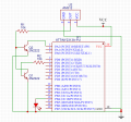
What I thought would happen with this circuit, when the LED is on, the first transistor is switched on, and the collector (which the PIR High is connected to) is brought to ground, and prevented from triggering the next transistor. If the LED is off, the PIR High can trigger the next transistor to bring the reset pin to low.
But... whats happening, the 1st transistor isn't bringing the PIR High to ground, and the 2nd transistor is bringing reset to low whenever the PIR is firing.
I've got an attiny85 on order, and am sure I can then do this with an interrupt from deep sleep on that (can probably also make it better, eg extend time to switch off with each PIR firing), but I'd really like to understand what I'm doing wrong with the transistors.
Thanks
I am trying to bring the reset to 0v on my attiny2313 (happened to have that one available for use)
Heres the reason, I got a PIR that only switches on (high) for 2 seconds.
What I am trying to do...
Switch on a LED for 3 minutes (attiny for the timing, code is working), then go to deep sleep.
After 3 minutes, if the PIR detects movement, reset the attiny (only if the LED is not currently on)
I used 2 pins for output, 1 for the LED, the other so a transistor can be biased when the LED is on.
I looked at using an interrupt, but the code was a little bit difficult for me to find/and follow for the 2313, so decided to use the reset...
What I thought would happen with this circuit, when the LED is on, the first transistor is switched on, and the collector (which the PIR High is connected to) is brought to ground, and prevented from triggering the next transistor. If the LED is off, the PIR High can trigger the next transistor to bring the reset pin to low.
But... whats happening, the 1st transistor isn't bringing the PIR High to ground, and the 2nd transistor is bringing reset to low whenever the PIR is firing.
I've got an attiny85 on order, and am sure I can then do this with an interrupt from deep sleep on that (can probably also make it better, eg extend time to switch off with each PIR firing), but I'd really like to understand what I'm doing wrong with the transistors.
Thanks
Attachments
-
 168.2 KB Views: 13


")


