 Facebook
 Google
 GitHub
 Linkedin
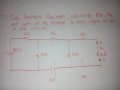
can anyone help me or explain me how to get the voltage in my circuits ,, i get the RL =8 ohms and 3.24324V ,, and my RTH is =60/11 ... now i put the voltage on the circuits and i dont know to get all the voltage .>> help me guys thanks
Help with thevenin problem
- Thread starter babyboang boang
- Start date

 help
help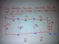


| Thread starter | Similar threads | Forum | Replies | Date |
|---|---|---|---|---|
|
|
thevenin equivalent problem.. need help how to solve ? | Homework Help | 19 | |
| R | Please help - Thevenin Problem | Homework Help | 19 | |
| E | Help with Thevenin problem | Homework Help | 11 | |
| U | Please I need your help with this thevenin problem !!!!!???????? | Homework Help | 19 | |
| U | Can u please help me with this thevenin problem ??? | Homework Help | 1 |


