Facebook
 Google
 GitHub
 Linkedin
Hi everyone,
I'm new to designing boards and coding for microcontrollers and I could really use some help getting started with the PIC18F45K22. I'm hoping someone here can offer some guidance or point me in the right direction to find resources to learn from.
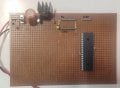
Specifically, I'm looking to design a board that can control a simple devices and I would like to use the PIC18F45K22 microcontroller for this project. However, I'm not quite sure where to begin with the design process or how to go about programming the microcontroller.
If anyone ( @JohnInTX ) has experience with designing boards and coding for the PIC18F45K22, MPLAB and PK3 I would really appreciate any advice or resources you could share with me. I'm eager to learn and I'm looking forward to getting started on this project.
Thank you so much for your help!
I'm new to designing boards and coding for microcontrollers and I could really use some help getting started with the PIC18F45K22. I'm hoping someone here can offer some guidance or point me in the right direction to find resources to learn from.
Specifically, I'm looking to design a board that can control a simple devices and I would like to use the PIC18F45K22 microcontroller for this project. However, I'm not quite sure where to begin with the design process or how to go about programming the microcontroller.
If anyone ( @JohnInTX ) has experience with designing boards and coding for the PIC18F45K22, MPLAB and PK3 I would really appreciate any advice or resources you could share with me. I'm eager to learn and I'm looking forward to getting started on this project.
Thank you so much for your help!
Attachments
-
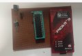 96.7 KB Views: 21