Help with sequential LED turn signals :(

Thread Starter

TuLaLiT

Joined Jul 27, 2009
7
Hi guys,

I'm planning on making sequential indicator turn signals for my car.

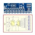
I bought this cheap LED chaser DIY kit from eBay. I've got it assembled but this kit isn't powerful enough to power up my LEDs

My question is how do I modify this kit so EACH channel can power up 6 x 20mA ( 120 mA in total ) ?
 

Attachments

ebeowulf17

Joined Aug 12, 2014
3,307
It's worth noting that @crutschow's approach uses low side switching (switching on the common, negative, ground, whatever you choose to call it, as opposed to keeping negative side connected and switching 12V side on and off)

This is certainly the best, simplest approach, but it's not always an option. If wiring constraints force you to use high side switching, you'd have three main options:
  1. Use PNP instead of NPN, and switch on high side directly. This approach also inverts logic (off becomes on and vice versa,) so it's probably not suitable in this circuit, where there isn't a straightforward way to fix the logic elsewhere.
  2. Use PNP high side switch, driven by NPN inverter stage. This uses double the components, but gives best performance for high side switching.
  3. Use NPN on high side in emitter follower configuration, which loses you roughly 0.7V, but otherwise should work well (correct logic is maintained, but LED/resistor combo sees ~11.3V when it would've gotten 12 with other configurations.)
Again, the low side switching method is certainly more straightforward if you can do it, but I thought I should mention the alternatives since automotive lighting is often switched high-side, and depending on how you're incorporating this into the vehicle, low side switching may be harder to implement.
 

Audioguru

Joined Dec 20, 2007
11,248
It is illegal to tamper with vehicle lighting in my country (Canada) because many people get it too dim, or too bright and with a narrow beam that cannot be seen at the sides.
 

crutschow

Joined Mar 14, 2008
34,280
Use NPN on high side in emitter follower configuration, which loses you roughly 0.7V, but otherwise should work well (correct logic is maintained, but LED/resistor combo sees ~11.3V when it would've gotten 12 with other configurations.)
Note that this approach does not require any resistor in series with the base, so is actually the simplest configuration.
 
Top