Help with sequential LED delay - 555 Timer

Status
Not open for further replies.

Thread Starter

preetham29

Joined Jun 21, 2018
2
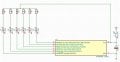
I need help with the series of monostable configuration of 555 Timers. The idea is to light up the different LEDs with different timings triggered by the falling edge of the previous timer, with the initial monostable setup being triggered by the switch. The first LEd lights up for 3 mins , then the next for 1 sec and the next for 1 min and so on for six LEDs.
However when i'm running the simulation in multisim , all the LEDs are already initially lit up except the first one. Can you please tell me what i'm doing wrong?
Any other ideas to light up LEDs one after another with their individual timings? i'm attaching the image below ( Ignore the resistor values , they're approximate , my issue is the LEDs lighting up without the previous 555's trigger as soon as i run the program )
mono_trigger.PNG
 

bertus

Joined Apr 5, 2008
22,277
Hello,

Perhaps you will need a power on reset.
Also the leds do not have any current limiting resistors.

Also the triggeling should be different.
Have a look at the schematic from the TI datasheet:

NE555_sequential timer.png

Bertus
 

Attachments

crutschow

Joined Mar 14, 2008
34,428
However when i'm running the simulation in multisim , all the LEDs are already initially lit up except the first one. Can you please tell me what i'm doing wrong?
The 555 Trigger input is a level detect, not edge detect, and at power-up all the 555 inputs are low so they all trigger on.
Thus the trigger inputs need to be AC coupled so they respond to the negative signal edge, as shown in bertus's post.
 

danadak

Joined Mar 10, 2018
4,057
His timing diagram shows one led on at a time, so two leds/pin,
one source drive, one sink drive, tristate both off. 3 pins. 1 pin
for switch.

Or one led / pin, switch turns on power to ATTINY to initiate sequence.
 

danadak

Joined Mar 10, 2018
4,057
1 ATTINY, 6 LEDs, 6 LED Rilims, 6 GPIO pins,
a switch as power switch for ATTINY to turn it
on and issue the sequence.

OR

1 ATTINY, 6 LEDs, 3 LED Rilims, 3 GPIO pins (2 LEDs/pin),
a switch as input to a pin to trigger the sequence.

for both a power source, and a bypass cap.

On power up GPIO pins in HiZ.

Total timing accuracy +/- 1% with user cal at test, or +/- 10% without.
 
Last edited:

ElectricSpidey

Joined Dec 2, 2017
2,776
The circuit posted by Bertus is ok, but with the outputs connected to ground via a LED and resistor I would worry about how the circuit will behave from startup, and probably drop in a RC net at each reset to insure they all start low.

The first one also needs a pullup resistor at the trigger, to avoid spurious starts. (not to mention the problems concerned by that switch also missing an AC input if the first timing cycle has to be shorter than the button push)
 
Last edited:

eetech00

Joined Jun 8, 2013
3,949
HI

Here's an option using CD14538B's.
I didn't draw the all six timers but three more could easily be added.
Each timer triggers on the falling edge of the previous timer

eT

SequencialTimer.png
 
Status
Not open for further replies.
Top