Help with RF Analyzer

Thread Starter

Sam Robinson

Joined Sep 8, 2022
8
Hi all,

I am new to the world of RF but would like to understand more so please have patience.

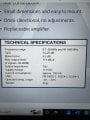
Firstly, can you explain to me how to digest and understand the information regarding dB, dBuV and dBIM values from the attached specs of an old TV FM antenna.
E.g
what values are considered normal as per todays standards?

what effect would be observed if a certain value is increased or decreased?

I’m familiar with impedance in terms of normal electrical circuits but in this case what does it mean?

Secondly, I would like to get an RF Analyzer in which I could connect the antenna in question to see what signal strength and frequencies are actually being received. I would also like the Analyzer to be able to tell me if there is RF interference around certain devices or areas of the vessel.

would I need a bunch of different types of antennas and attach them to the Analyzer then just test the spectrum for the given antenna at the location I wish to test?

how would I go about choosing an Analyzer that could fulfill my needs? For example that wouldn’t be damaged by connecting the TV FM antenna?

sorry for all the novice questions but I’m a mechanical engineer that’s been given the responsibilities of an electrical/AV/IT engineer and unfortunately for me fault finding RF frequencies falls under my responsibility now.
 

Attachments

Irving

Joined Jan 30, 2016
3,843
Phew, sounds like you've been chucked in the deep end! A little more explanation on the scenarios you are working with would help. It sounds like you're talking about EMC testing?

dBuV = signal strength relative to 1uV. calculated as dB = 20log(S1/S2), so 111dBuV = 0.355V approx. across the same impedance.

dBIM I'm not familiar with. It could be meaning dB1m i.e. dB relative to 1mW of power (usually written dBm), so its saying the maximum output is 111dBuV when receiving 2 signals, both -50dBm . Power is calculated as 10log(P2/P1) so -50dBm = 10nW

The dB gain is simply how much better this antenna is compared to a simple 1/2 wave dipole.

http://www.cantwellengineering.com/calculator has a useful range of calculators for dBxx and impedances.
https://www.antenna-theory.com/definitions/decibels.php
 
Last edited:

Thread Starter

Sam Robinson

Joined Sep 8, 2022
8
Phew, sounds like you've been chucked in the deep end! A little more explanation on the scenarios you are working with would help. It sounds like you're talking about EMC testing?

dBuV = signal strength relative to 1uV. calculated as dB = 20log(S1/S2), so 111dBuV = 0.355V approx. across the same impedance.

dBIM I'm not familiar with. It could be meaning dB1m i.e. dB relative to 1mW of power (usually written dBm), so its saying the maximum output is 111dBuV when receiving 2 signals, both -50dBm . Power is calculated as 10log(P2/P1) so -50dBm = 10nW

The dB gain is simply how much better this antenna is compared to a simple 1/2 wave dipole.

http://www.cantwellengineering.com/calculator has a useful range of calculators for dBxx and impedances.
https://www.antenna-theory.com/definitions/decibels.php
Thanks for the reply,

Yes I have certainly been chucked in the deep end regarding RF.

I don’t know exact scenarios but we use MF and VHF radio communications with their dedicated antennas, hand held UHFs, the TV FM in question, Wi-Fi. I would like to be able to see the RF spectrum to aid with fault finding.

I’d also like to know if/which analyser can be connected to both the ships antenna and also use its own antenna in order to see a specific frequency at a specific location. For example, to test for interference at a GPS receiver, radar, various communication or control devices etc.

Then of course, I would need to learn how to make sense of the data produced by the analyser
 
Last edited:

Irving

Joined Jan 30, 2016
3,843
Well you'll need a spectrum analyser of some sort. You don't say what frequency range you need to cover but from the equipment you describe I'm guessing from 100kHz to 6GHz (assuming 5GHz WiFi). Such devices don't come cheap... Have a look here to start.

From your environment I suspect you need portability and battery operation and ruggedness... Tektronix have a range of field-oriented devices such as the RSA507A which, coupled with a rugged laptop/tablet should meet your needs. I have no association with Tektronix (other than to drool over what I'll never afford!), there are many options from several suppliers.
 

Thread Starter

Sam Robinson

Joined Sep 8, 2022
8
Yeah I’m not sure about exact frequencies without checking all specs of all the equipment.

Those looks great what you sent to me but unfortunately I’d probably have a budget of say 500 euros or so… I know I wouldn’t get a top of the range piece of equipment with all bells and whistles but something that would cover the VHF range would be a good start.

As I said before, if I could connect ships antennas to it as well as use it in a “wireless” setting then that would be great. I’m not sure if this is a standard thing but reading the specs of some cheap analysers I seen they had a max dBm rating and thus I’d need something that could tolerate the ships antennas which I assume (but still need to check) would be on the stronger side of things
 

Irving

Joined Jan 30, 2016
3,843
Connecting a spectrum analyser to the ships antenna isn't an issue - all such kit has a maximum signal input; you'd need an attenuator box to limit the signal level, and of course make sure no transmission occurs while its connected.

Hmmm, you're not going to get much for 500euros. But there are a few options and this is arguably a good starting point:

https://www.amazon.co.uk/dp/B089QBXX6C £460
1662667246892.png
 

tautech

Joined Oct 8, 2019
383
Those looks great what you sent to me but unfortunately I’d probably have a budget of say 500 euros or so…
Then don't expect much with such a frugal budget so go back and ask those that think you can perform magic to give hints on how to proceed however with treble that budget and you can get a quite useful 2.1 GHz analyzer.

So you need an analyzer so before you start looking define your needs and more particularly the frequency range of interest.
Those with TG capabilities open further possibilities of antenna and filter analysis as well as your basic RF In analysis.
You can do a lot with a TG and return loss bridge however without some experience accurately interpreting results can be difficult.

Do you need a portable device and if so how portable, hand held or say 5kg of some 20kg monster that won't slide off the bench in high seas ?

Accurately defining needs is key to getting good advice and after a couple of analyzers I've settled on a SVA1032X as a good all-round instrument for advanced hobbyist or semi professional needs as even though it's a single port VNA too the VNA capabilities one can find more useful than just a SA, especially for antenna development work.
EMI/RFI compliance and pre-compliance work is becoming a significant requirement for analyzers these days too and analyzer manufacturers have responded to these calls of additional capability with adding specific EMI analysis suites/options for those that need this capability and if our experience is anything to go by EMI precompliance capability accounts for 50+% of our sales.

A guide to help you on your journey:
https://siglentna.com/application-note/spectrum-analyzer-selection/
 

Irving

Joined Jan 30, 2016
3,843
So you need an analyzer so before you start looking define your needs and more particularly the frequency range of interest.
Those with TG capabilities open further possibilities of antenna and filter analysis as well as your basic RF In analysis.
You can do a lot with a TG and return loss bridge however without some experience accurately interpreting results can be difficult.

Do you need a portable device and if so how portable, hand held or say 5kg of some 20kg monster that won't slide off the bench in high seas ?

Accurately defining needs is key to getting good advice
I think the problem that Sam has is that he has, as yet, no in-depth understanding of the types of measurements he needs to be making or how to make them. He is on a steep learning curve. Hell, I've many years of RF experience but "fault finding RF frequencies falls under my responsibility now" on board a ship would still be a daunting task!

For the record I spent several years designing & testing ground-to-air C3S for fighters & bombers and some land-based equipments but nothing directly ship-related. I doubt many of us would be able to imagine how to do this without being on-site.
 

tautech

Joined Oct 8, 2019
383
Irving
Certainly as it has just been a few years ownership of SA's that has led me by the nose into this field of black magic however as a seller of such equipment I need at least have some command of the basics and although I don't use an analyzer every day I now have enough understanding of those we sell to advise anyone seeking one.
At one time most analyzers were too delicate to let anyone lose on one however today they are very different using AC coupled inputs and with 50V max ratings but at some cost to DANL but not so excessive to limit them from normal operation and at $1500 not beyond the reaches of the RF enthusiast.
Like with a scope but arguably much worse for an analyzer the initial outlay is just the start as a good range of accessories can set you back a few hundred more.
 

Thread Starter

Sam Robinson

Joined Sep 8, 2022
8
I think the problem that Sam has is that he has, as yet, no in-depth understanding of the types of measurements he needs to be making or how to make them. He is on a steep learning curve. Hell, I've many years of RF experience but "fault finding RF frequencies falls under my responsibility now" on board a ship would still be a daunting task!

For the record I spent several years designing & testing ground-to-air C3S for fighters & bombers and some land-based equipments but nothing directly ship-related. I doubt many of us would be able to imagine how to do this without being on-site.
Yes, exactly as Irving stated, my problem is I don’t know enough about it to understand what I actually need unfortunately.

Therefore I’d need something more on the simpler side of things, an example would be, our Ku band VSAT connection is slow or non existent, I’d like to see if the antenna is actually receiving frequencies between 12-18Ghz.

Now as my budget is tight, I understand I’m not going to find a device that will cover all frequencies etc etc. we have a lot of sensitive devices on board that can be effected by EMI, for example a data communication cable may have been ran too close to an AC cable which can cause corruption of the data. As there are kilometres of cabling l, I can’t simply identify if said cable is AC or causing any interference in general.

Correct me if I am wrong but a 50hz AC cable could produce interference at 50hz so basically I’d have to choose a device that can cover the frequencies that are of more interest to me, that being 50hz assuming my above statement is correct and VHF frequencies as a lot of equipment runs on those frequencies. 2.4 or 5Ghz would also be useful but I’d have to weigh up frequencies covered vs cost and choose a device that way. Again, if the device is cheaper I’d assume less information can be read from the device, which at my current level of understanding will probably be a good thing for me. With a bit of research and studying I’d like to be able to get a rough idea of what is going on in a given situation regarding EMI and fault finding the band of frequencies that would be covered by the device I would buy.

I hope this makes sense because due to my lack of understanding, I can barely explain what I need which means it is understandably difficult for you guys to help me.

In short, I’m looking for a device to pull off basic information about RF that will be used mainly to aid in fault finding certain systems
 

Irving

Joined Jan 30, 2016
3,843
In short, I’m looking for a device to pull off basic information about RF that will be used mainly to aid in fault finding certain systems
And thats where the difficulty lies because those sorts of issues can take so many forms even capturing the event let alone analysing it can & will be an uphill task.

To take your example.. a 50Hz AC feed in itself is unlikely to cause an issue and data cables are generally screened from external interference. But should that screening be compromised at a joint through corrosion (not uncommon on a ship I'd hazard) and, independently, a fault occur in equipment supplied by that feed which caused intermittent current spikes, which by definition are wideband across a range of frequencies, then there is a possibility that data corruption could occur. Then the problem is many-fold, identify the source of the spikes, correlate that with the data corruption, locate the area where the corruption occurs and find the breach in the screening. A spectrum analyser may be useful in such circumstances - possibly to help locate the noise spikes or to track down the break in the screening (if EMI gets in, its likely the data traffic radiates out too, albeit at a very low level) using accessories such as a wideband directional antenna.

Therefore I’d need something more on the simpler side of things, an example would be, our Ku band VSAT connection is slow or non existent, I’d like to see if the antenna is actually receiving frequencies between 12-18Ghz.
Another different issue: The 12-18GHz will be down-converted at the antenna to a lower frequency for onward transmission to the receiving equipment. Its quite likely you can't physically get to the 12-18GHz feed (apart from 12 - 18GHz is well outside the range of any equipment you're likely to be able to afford any time soon) and its likely you'll only be able to look at the output.
 
Last edited:

Thread Starter

Sam Robinson

Joined Sep 8, 2022
8
And thats where the difficulty lies because those sorts of issues can take so many forms even capturing the event let alone analysing it can & will be an uphill task.

To take your example.. a 50Hz AC feed in itself is unlikely to cause an issue and data cables are generally screened from external interference. But should that screening be compromised at a joint through corrosion (not uncommon on a ship I'd hazard) and, independently, a fault occur in equipment supplied by that feed which caused intermittent current spikes, which by definition are wideband across a range of frequencies, then there is a possibility that data corruption could occur. Then the problem is many-fold, identify the source of the spikes, correlate that with the data corruption, locate the area where the corruption occurs and find the breach in the screening. A spectrum analyser may be useful in such circumstances - possibly to help locate the noise spikes or to track down the break in the screening (if EMI gets in, its likely the data traffic radiates out too, albeit at a very low level) using accessories such as a wideband directional antenna.


Another different issue: The 12-18GHz will be down-converted at the antenna to a lower frequency for onward transmission to the receiving equipment. Its quite likely you can't physically get to the 12-18GHz feed (apart from 12 - 18GHz is well outside the range of any equipment you're likely to be able to afford any time soon) and its likely you'll only be able to look at the output.
I’m sure it’s not highly likely but it’s definitely possible based on the systems and devices installed within relatively close proximity to one another. VFDs, DC converters, incorrectly grounding of cable shields etc etc.

I’ve found a low AC voltage on a DC cable for a piece of control equipment in the past which I can only assume was caused by EMI. I also know for certain that I have NMEA data corruption between a GPS receiver and NMEA buffer, same on a anemometer to its buffer.

In the case of the corrupted NMEA sentences, I’d use the analyser to leave by the suspect site, for say overnight, then ideally check the data that was logged for EMI and compare to the NMEA data and look for patterns in spikes vs data corruption.

Would the analyser that you proposed me for £460 be capable of something like this?
 

Irving

Joined Jan 30, 2016
3,843
Would the analyser that you proposed me for £460 be capable of something like this?
Sadly not. Nor would most of the cheap ones either. Since you don't know whats causing the issue you need to do a wideband capture at a fast scan rate, since the EMI may only last a few mS, and capture continuously for several hours to be able to do a post run correlation. That implies a high-spec SA. I'd approach the problem differently. I'd capture the NMEA data using a custom programmed microController (passing it onto the real recipient as well) until an error occured and use that event to trigger a stop command to the SA to save the information from just the last few scans. That would be doable with a much lower spec (albeit still ~£1500-£2000) device. Indeed its likely that the microcontroller could restart the test to get multiple hits over an extended period.
 

Irving

Joined Jan 30, 2016
3,843
I’ve found a low AC voltage on a DC cable for a piece of control equipment in the past which I can only assume was caused by EMI.
Almost certainly a ground loop caused by different ground potentials at each end of the link due to poor/incorrect earth bonding - presumably the ships hull is the equivalent to the earth rod in a land installation, or a car's chassis/body in an automotive environment.
 

tautech

Joined Oct 8, 2019
383
Almost certainly a ground loop caused by different ground potentials at each end of the link due to poor/incorrect earth bonding - presumably the ships hull is the equivalent to the earth rod in a land installation, or a car's chassis/body in an automotive environment.
Yes all it takes is for someone unfamiliar with marine wiring to use the hull or part of for current return and therein a electrolysis corrosion situation is born.
 

Thread Starter

Sam Robinson

Joined Sep 8, 2022
8
Yes all it takes is for someone unfamiliar with marine wiring to use the hull or part of for current return and therein a electrolysis corrosion situation is born.
DC is floating and AC should be earthed back to a limited number of points on the hull to prevent electrolysis as tautech said. Emphasis on the word “should” as many people have came and gone.

I’ll try one of the RF explorer models and start my steep learning curve. Thanks for the replies, much appreciated
 

Irving

Joined Jan 30, 2016
3,843
I’ll try one of the RF explorer models and start my steep learning curve. Thanks for the replies, much appreciated
You're welcome.

While not a solution to your issues, it won't hurt to gain experience of such a device and it's limitations. A wander around the ship with one might open up areas of interest for more detailed examination later.

Feel free to check back in for more help or discussion & welcome to AAC!
 
Top