Facebook
 Google
 GitHub
 Linkedin
I have been working with a voltage controlled current source circuit mainly made out of a 741 opamp and a 2N3906 PNP transistor. The current source is needed to create control current for an operational transconductance amplifier that in turn will be part of a voltage controlled oscillator. The output of the current source should sweep between 0 to 0.5mA in a linear fashion.
I got the current source idea from a lecture on OTAs found here: http://users.ece.gatech.edu/~lanterma/ems/
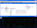
Here's a schematic of the current source, with the voltage values I've recorded. VCC should be set at 8.15V, forgot about that, sorry:

The operation, in theory, should work as follows:
The opamp V+ terminal connects to ground. This ensures that the opamp V- terminal (in the ideal case) is also set to ground. The current flowing between the VCC input (at 8.15V) and the V- terminal should be:
8.15V / 100K = 81.5uA
Since V- is virtual ground (with infinite impedance into the opamp), the value at the end of the emitter should be -VCC as the current flowing into and out of the V- node should be equal, or 81.5uA.
When calculating the emitter current, one then looks at the 100K and 22K resistors like they are in parallel because of the virtual ground at V- and actual ground (I'm not so certain about this). Therefore, the emitter current should be:
-Vi / (100K || 22K) = (-Vi)(0.055) mA
Which leaves you at approximately a linear sweep from 0 to 0.45mA with 8.15V being your top value. I'm using 9V batteries here if you haven't guessed already. The source output is the collector.
The problem I'm having is that I'm getting -5mA out of the collector not 0.5mA. I've checked this a number of times. -5.37V / 1K is certainly -5.37mA.
Things I've done:
1. Used a 10K pot to offset null the opamp. Is this ever really possible? I've gotten it to where blowing on the pot will change which rail the opamp hits, but I never get 0V.
2. Checked the PNP terminals a number of times to ensure the emitter and collector are the proper terminals.
3. Rechecked the pins on the opamp to ensure the proper connections.
I guess the real question is, does this circuit make sense? Should I be assuming a real opamp can create that virtual ground? Currently it won't budge from around 1.3V or so.
Thank you very much for any help you can provide. Sorry for the long post.
EDIT:
I forgot to add that the opamp Vout is -6.27V.
I got the current source idea from a lecture on OTAs found here: http://users.ece.gatech.edu/~lanterma/ems/
Here's a schematic of the current source, with the voltage values I've recorded. VCC should be set at 8.15V, forgot about that, sorry:
The operation, in theory, should work as follows:
The opamp V+ terminal connects to ground. This ensures that the opamp V- terminal (in the ideal case) is also set to ground. The current flowing between the VCC input (at 8.15V) and the V- terminal should be:
8.15V / 100K = 81.5uA
Since V- is virtual ground (with infinite impedance into the opamp), the value at the end of the emitter should be -VCC as the current flowing into and out of the V- node should be equal, or 81.5uA.
When calculating the emitter current, one then looks at the 100K and 22K resistors like they are in parallel because of the virtual ground at V- and actual ground (I'm not so certain about this). Therefore, the emitter current should be:
-Vi / (100K || 22K) = (-Vi)(0.055) mA
Which leaves you at approximately a linear sweep from 0 to 0.45mA with 8.15V being your top value. I'm using 9V batteries here if you haven't guessed already. The source output is the collector.
The problem I'm having is that I'm getting -5mA out of the collector not 0.5mA. I've checked this a number of times. -5.37V / 1K is certainly -5.37mA.
Things I've done:
1. Used a 10K pot to offset null the opamp. Is this ever really possible? I've gotten it to where blowing on the pot will change which rail the opamp hits, but I never get 0V.
2. Checked the PNP terminals a number of times to ensure the emitter and collector are the proper terminals.
3. Rechecked the pins on the opamp to ensure the proper connections.
I guess the real question is, does this circuit make sense? Should I be assuming a real opamp can create that virtual ground? Currently it won't budge from around 1.3V or so.
Thank you very much for any help you can provide. Sorry for the long post.
EDIT:
I forgot to add that the opamp Vout is -6.27V.
Last edited: