Facebook
 Google
 GitHub
 Linkedin
I am definitely a newb to working with circuits. I am an IT guy, so this is my first attempt at building circuits. I am making some dimmable leds and going to control them via a PIC using pwm. The pwm output from the PIC is a 400Hz signal and 0-5V. My drivers are Meanwell ELN-60-48 P that takes a pwm signal 0-10V, but must be in the range of 100Hz - 3KHz. I cannot use a low pass filter or it will turn my digital square wave into a rounded wave.
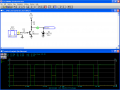
I have successfully built a simple circuit using a rail to rail op amp that takes the pwm signal and doubles the voltage output perfectly as the pwm signal rises and falls from 0-5V. However, what I do not know is if the frequency has changed and I assume since the wave input is a digital square wave, that the output is the same. I do not have an oscilloscope to check out the frequency and the wave, so I have some newbie questions:
If my input into the RTR op amp is 400Hz and the voltage doubles, will the op amp double the frequency also? Or is the frequency going to be sporadic and possibly rise above 3 KHz? If so, how can I limit or set the frequency without turning this into analog and keeping the digital pwm signal?
Simple Voltage Doubler:
2 - 10k ohm resistors 1% self explanatory for doubling voltage
1 - 4.02K resistor 1% on the pwm input
1 - .1 uf capacitor 3% to pwm input and ground
1 - TLV272 RTR dual op amp
12V power supply.
It is a pretty basic non-inverted op am design.
Would it be easier to use an lm555 timer? I am sure I have several options on this, but again some guidance in the right direction would be greatly appreciated.
I was thinking that I might have to run this through a second pass on the op amp as a comparator to produce the pwm...
Last edited: